GFK-2958E RSTi-EP User Manual 239
5.22 Analog Input Module EP- 3264
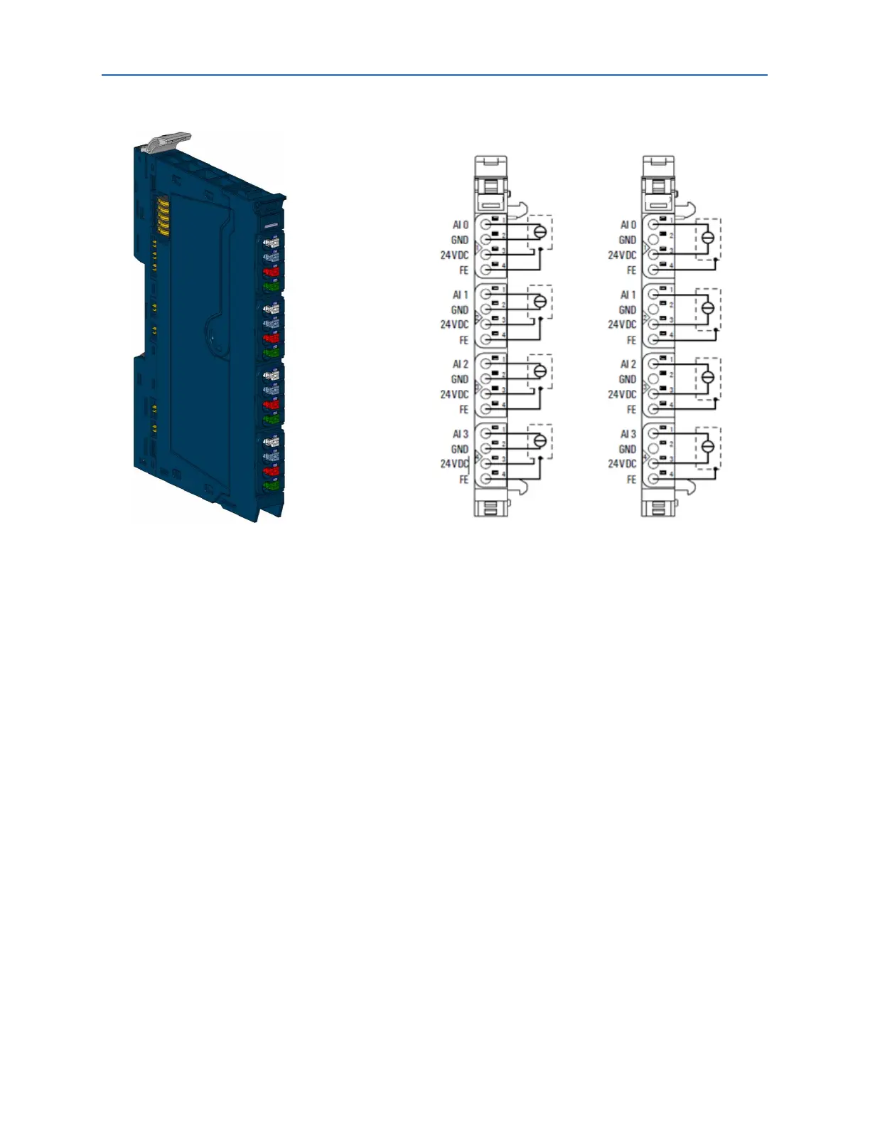
Analog Input Module EP-3264 Connection Diagram EP-3264
(left 3/4-wire sensor with sensor wiring via electronics,
right: 2-wire sensor with sensor wiring via electronics)
The EP-3264 analog input module can record up to 4 analog sensors with ±10 V, ±5 V, 0-10 V, 0-5 V,
2-10 V, 1-5 V, 0-20 mA or 4-20 mA. The resolution is 16 bit per channel. Sensors can be connected to
each connector in a 2-wire, 3-wire or 3-wire connection + FE. The measurement range is defined
using parameterization. Two status LED are assigned to each channel. The module electronics supply
the connected sensors with power from the input current path (I
IN
).
Each sensor output is loadable with 500 mA and protected agains overcurrent. The inputs are
protected against voltage surges and overcurrent. Voltages that exceed ±30 V may cause the
destruction of the module. As a protection against overcurrent, the module temporarily switches to
voltage mode.
The module provides individual channel diagnosis with channel related error messages.

 Loading...


