14.2 Grounding
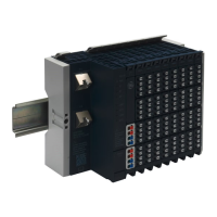
Proper grounding of the CPE100 is essential using the provided ground terminal
as shown in the below figure. Use a 16-22 AWG braided wire with lugs to connect
the ground terminal of CPE100 to DIN Rail. The DIN rail into which this product will
be mounted must be grounded as per the instructions provided in RSTi-EP System
Manual, GFK-2958.
Figure xx: Ground Terminal of EPSCPE100
14.3 Replacement of internal Super Capacitor (EPSACC001)
EPSCPE100 have internal supercap circuitry, which is replaceable with a new one EPSACC001.
The replacement procedure is given below.
1. Power off the unit (EPSCPE100) and wait for 5 minutes to allow the internal Super
Capacitors to discharge completely.
2. Detach the side panel cover by removing the (M3) screws with a screw driver as shown
below.
3. Detach the Super Capacitor card from the carrier board using a screw driver (M2.5) as
shown below.

 Loading...