EasyManuals Logo

GE RSTi-EP User Manual

GE RSTi-EP
425 pages
To Next Page IconTo Next Page
To Previous Page IconTo Previous Page
Page #109 background imageLoading...
Page #109 background image
Chapter 5 Detailed Descriptions of I/O Modules
GFK-2958E RSTi-EP User Manual 105
5.4 Digital Input Module EP-1804
EP-1804
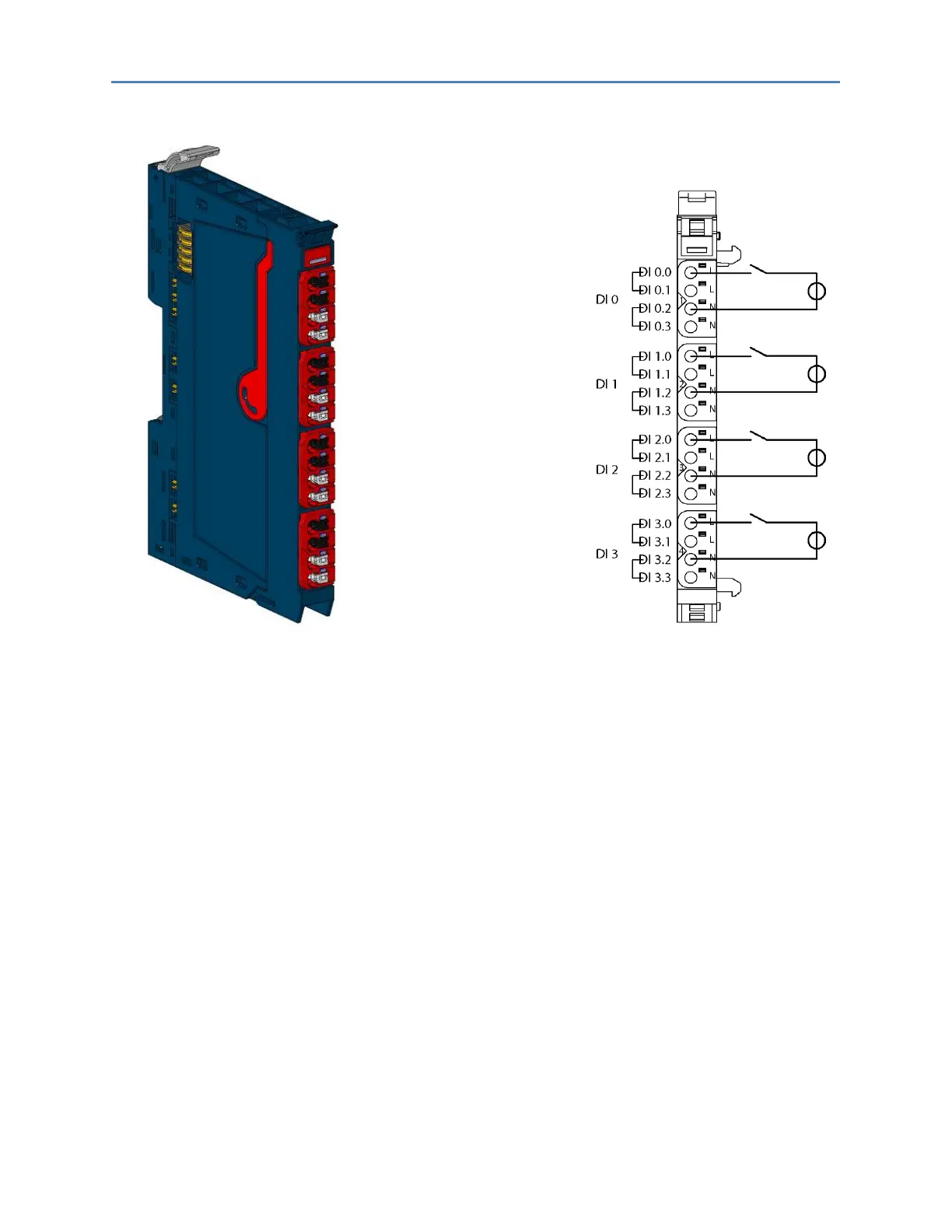
Digital Input Module EP-1804 Connection Diagram EP-1804
The digital input module EP-1804 can detect up to 4 binary control signals. One sensor can be
connected to each connector using a 2-wire connection. Both L and N connections of each input are
bridged internally. The four inputs are galvanic isolated, they can be supplied with input voltages
between 110V AC and 230V AC. Solely AC measurements can be run.

Table of Contents

Other manuals for GE RSTi-EP

Questions and Answers:

Question and Answer IconNeed help?

Do you have a question about the GE RSTi-EP and is the answer not in the manual?

GE RSTi-EP Specifications

General IconGeneral
BrandGE
ModelRSTi-EP
CategoryController
LanguageEnglish

Related product manuals