GFK-2958E RSTi-EP User Manual 181
5.15 Digital Counter Module EP- 5112
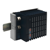
Digital Counter Module EP-5112 Connection Diagram EP-5112
The digital counter module EP-5112 can read square-wave signals (for example, from an incremental
encoder) with a maximum input frequency of 100 kHz. Depending on the operating mode, both 32-
bit counters can count up or down independent of each other in a preset range of values. The
counters can be controlled via software by setting the appropriate control word.
In mode Pulse and Direction, channel CH0 A and CH1 A respectively is used as the input, channel CH0
B and CH1 B respectively is used as a direction-determining input. In incremental mode, an
incremental encoder with track A and B can be connected. A status LED is assigned to each channel.
The module electronics supply the connected sensors with power from the input current path (I
IN
).
• Two 32-bit counters (AB), invertible, 24 V DC
• Counting frequency 100 kHz max (AB 1/2/4-times sampling or pulse and direction)
• Comparison value, setting value, input filter (parametrizable)
• Alarm and diagnostic function with μs time stamp
• μs time stamp for value counting (for example, for speed measurements)

 Loading...