GFK-2958E RSTi-EP User Manual 25
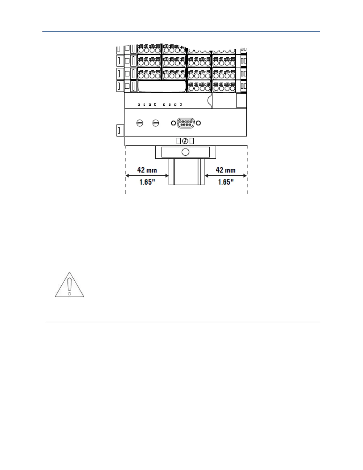
Installation Position of the RSTI-EP Station on the DIN Rail (Vertical Installation)
A RSTi-EP station may only be installed in this sequence (starting from the left/bottom):
• End bracket
• Network adapter
• Up to 82 modules (including max. 64 active modules)
• End plate and end bracket
A maximum of three passive modules (potential distribution module, power-
feed module or blank module) may be placed in successive positions. Then at
least one active module must follow.
3.1.1 Arrangement of Safe Power-feed Modules
A safe power-feed module EP-19xx module can be positioned anywhere in the RSTi-EP station. All the
following output modules (except for the EP-2814 and EP-2714 relay modules) up to the next EP-19xx
module are safely disconnected (safety segment). Multiple EP-19xx modules/safety segments can be
arranged within a station.
Note: When using RSTi-EP EP-19xx modules, also refer to the Modules for Functional Safety Manual
(GFK-2956).

 Loading...


