Chapter 5 Detailed Descriptions of I/O Modules
GFK-2958E RSTi-EP User Manual 229
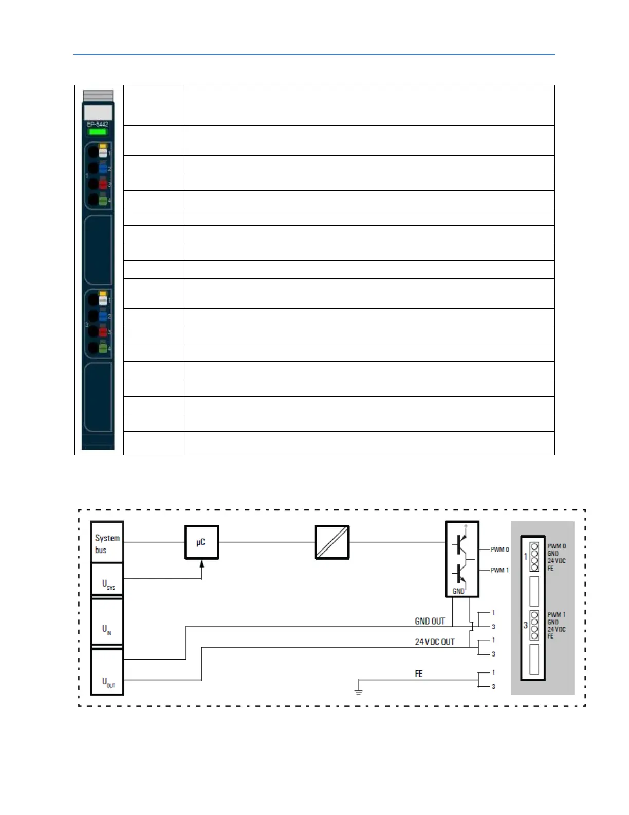
LED Indicators EP-5442
Green: Communication over the system bus
Red: Module System Fault or Diagnostic Fault
Yellow: PWM output 0 – 100%, P-switching
Yellow flashing at 2 Hz: PWM output 0 is > 0 and < 100%, PN-switching or P-switching
Yellow: PWM output 1 – 100%, P-switching
Yellow flashing at 2 Hz: PWM output 0 is > 0 and < 100%, PN-switching or P-switching
For error messages refer to the chapter, LED Indicators and Troubleshooting.

 Loading...


