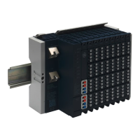
Chapter 5 Detailed Descriptions of I/O Modules
GFK-2958E RSTi-EP User Manual 271
Specifications EP-4264
Process, parameter and diagnostic data depend on the network
adapter used (refer to the table in the section, Order and
Arrangement of the Modules)
RSTi-EP I/O communication bus
1. Voltage (0 – 5 V, ±5 V, 0 – 10 V, ±10 V, 1 – 5 V, 2 – 10 V)
2. Current (0 – 20 mA, 4 – 20 mA)
0.1 % FSR max., 0.05 % FSR typ.
20 ppm voltage / 31 ppm current measurement / K
Max. error between T
min
and T
max
Crosstalk between the channels
≥ 1 kΩ (at > 50°C (122 °F) max ambient temperature, total sensor
current of 10 mA per channel but 25 mA per module)
2-wire (current and voltage; automatic detection), 4-wire (voltage)
Individual channel diagnosis
Current consumption from system current path
I
SYS
,
Current consumption from output current path
I
OUT
For additional general data, refer to the section, General Technical Data for I/O Modules.

 Loading...