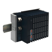
Chapter 5 Detailed Descriptions of I/O Modules
GFK-2958E RSTi-EP User Manual 278
Specifications EP-3704
Process, parameter and diagnostic data depend on the
network adapter used (refer to the table in the section, Order
and Arrangement of the Modules)
RSTi-EP I/O communication bus
Pt100, Pt200, Pt500, Pt1000, Ni100, Ni120, Ni 200, Ni500,
Ni1000, Cu10, 40 Ω, 80 Ω, 150 Ω, 300 Ω, 500 Ω, 1 kΩ, 2 kΩ, 4 kΩ
max. 0.2 % FSR / 0.3 % FSR for Ni sensors / 0.6 % FSR for Cu10
depending on the sensor type 0,75 mA (Pt100, Ni100, Ni120,
Cu10, 40 Ω, 80 Ω, 150 Ω, 300 Ω) or 0,25 mA (Pt200, Pt500,
Pt1000, Ni200, Ni500, Ni1000, 500 Ω, 1 kΩ, 2 kΩ, 4 kΩ)
Max. wire resistance / measurement range
2.5 Ω / 40 Ω, 5 Ω / 80 Ω, 10 Ω / 150 Ω and Cu10, 25 Ω in all
other measuring ranges
-200 to +850°C (-328 to 1562 °F)
Common mode input voltage range
Channel to channel: max. ±2 V
Channel to voltage supply: max. ±50 V
Reverse polarity protection
Individual channel diagnosis
Current consumption from system current path I
SYS
,
Current consumption from input current path I
IN
For additional general data, refer to the section, General Technical Data for I/O Modules.

 Loading...