Chapter 4 Detailed Descriptions of the Fieldbus Network Adapters
GFK-2958E RSTi-EP User Manual 63
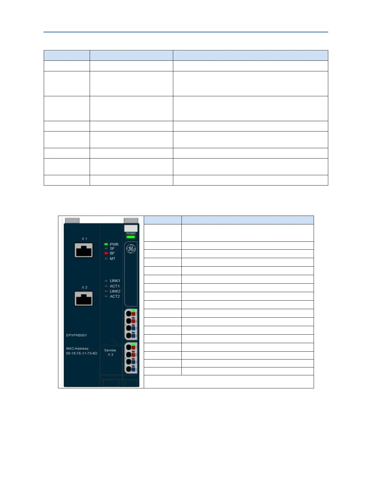
LED Status Indicators EPXPNS001
Green: Supply voltage connected
Red: Configuration error, or error in the PROFINET Scanner, or
error in a module, or there is a new diagnostic report
Red flashing: Station in Force mode
Red: No connection to the fieldbus
Red flashing: Configuration error, no connection to the control
unit, or error in the parameter set
Yellow: Error on the system bus or the fieldbus
Green: Connection established between port 1 of the PROFINET
Scanner and another field device
Yellow flashing: Data being exchanged on port 1
Green: Connection established between port 2 of the PROFINET
Scanner and another field device
Yellow flashing: Data being exchanged on port 2
Green: Supply voltage > 18 V DC
Red: At least one current path < 18 V
Green: Input current path supply voltage > 18 V DC
Red: Input current path supply voltage < 18 V DC
Red: Internal fuse defective
Green: Output current path supply voltage > 18 V DC
Red: Output current path supply voltage < 18 V DC
Red: Internal fuse defective
For error messages, refer to the Chapter, LED Indicators and Troubleshooting.

 Loading...


