Menu selection Description
Const. Setting Allows to set the values for additive and multiplying constant.
Factory set-
tings
Allows to reset all instrument settings to the factory default.
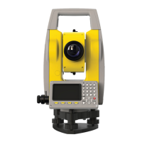
12.4 Adjust Index Error
The vertical circle should read exactly 90° (100 gon) when the line of sight is horizontal. Any
deviation from this figure is termed vertical index error. This is a constant error that affects all
vertical angle readings.
a Mechanical vertical axis of the instrument,
also called standing axis
b Axis perpendicular to the vertical axis. True
90°
c Vertical angle is reading 90°
d Vertical index error
☞
By determining the vertical index error
the electronic level is adjusted automat-
ically
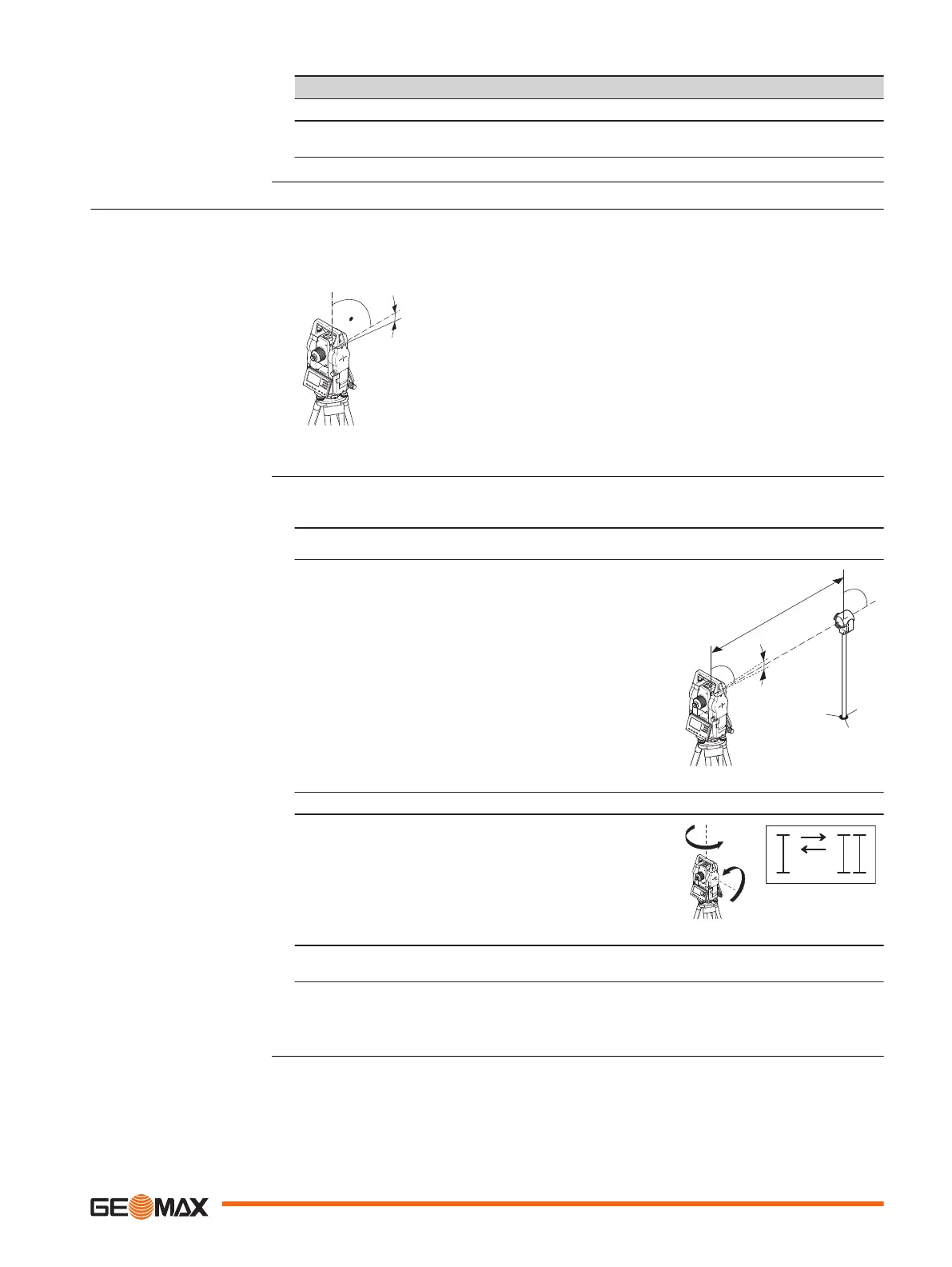
1. Level the instrument with the electronic level. Refer to "Setup step-by-step" and
"Electronic level and laser plummet".
☞
Activate the compensator before starting the adjustment procedure.
2. Aim at the target point.
3. Press OK to measure to the target point.
4. Change face and aim at the target point again
5. Press OK to measure to the target point.
The old and new calculated values are displayed.
6. Either:
•
Press OK to save the new calibration data, or
•
Press ESC to exit without saving the new calibration data.
Vertical index error
Adjust Index Error step-
by-step
Check & Adjust 91
 Loading...