Gilson 157/159 UV-VIS Detectors User’s Guide B-13
Front Panel Control
B
Setup Menu
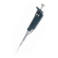
Intensity
The intensities in channel C1 are displayed. Monitor source can be selected
(absorption, signal channel, reference channel).
For check the functionality of the lamp, the two light intensity values I-sig
and I-ref provide useful information. The right column notes the absolute
light intensity that the signal and reference channels in the UV-maximum
measure after a calibration. The values are independent from the
integration time default setting and can, therefore, be used as a spectra
sources quality gauge. The value I-sig allows you to draw conclusions about
the measurement situation (installed flow cell type, solvent used, bubble free, etc.).
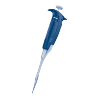
Scan (159 UV-VIS Detector Only)
The integrator channel and the speed can be specified for the scan output.
The detector offers two integrator outputs that are accessible at the RCA
ports on the back of the detector.
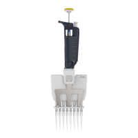
Analog out
Here the offset (moving the baseline) and scaling (in AU/V) of the integrator
outputs can be set.
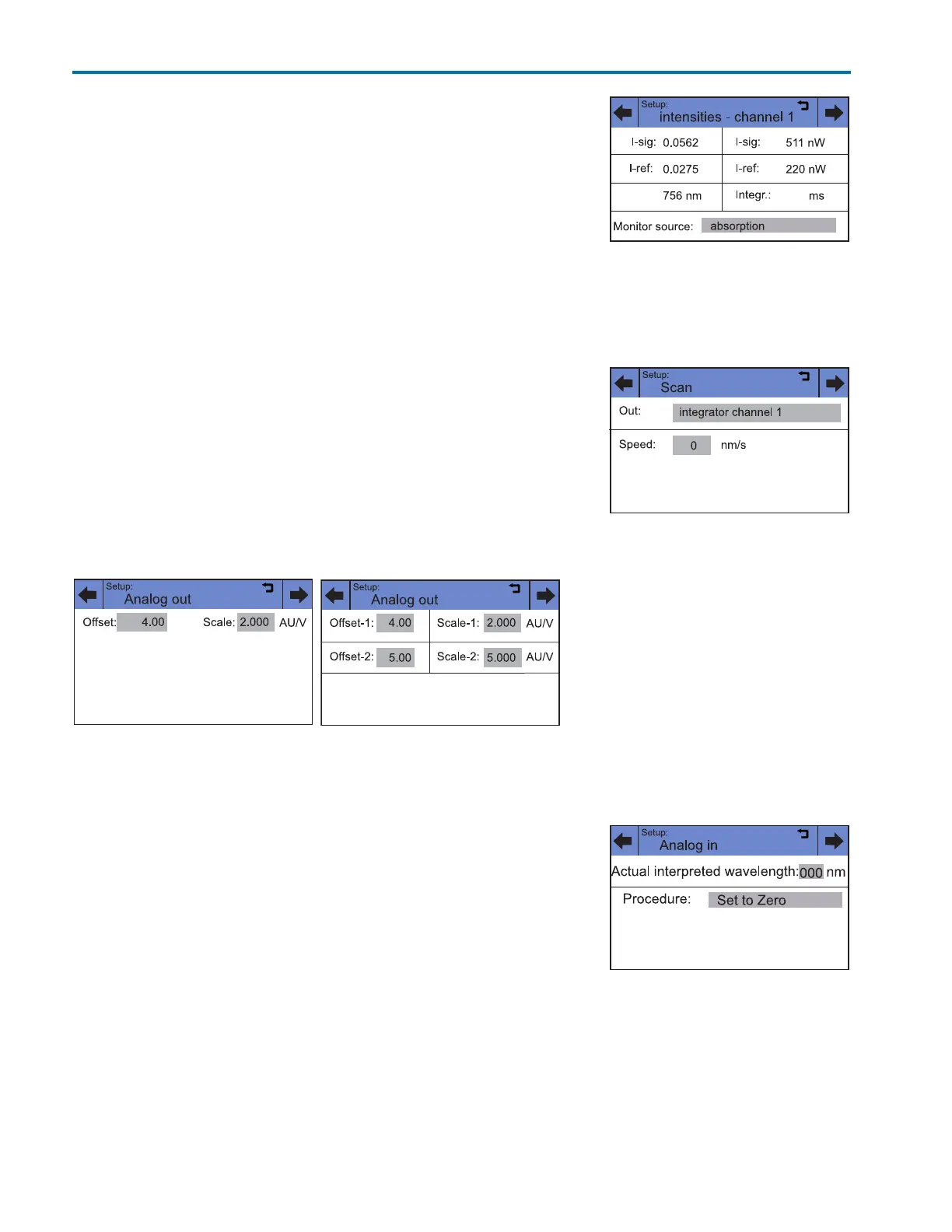
Analog in
The external l input on the back of the device enables external control of the
detector through a positive analog voltage that is applied against AGND.
By selecting Set to zero, a voltage can be defined as the spectral zero point
for the wavelength 000 nm. Typically, a voltage of 0 is used in this case.
If the control voltage is raised, then the actual interpreted wavelength field
shows the corresponding wavelength with a scaling of 100 nm/V. The
scaling can be changed with the number keys that appear after touching
the field.
Note: For optimal linearity, a scaling of 100 nm/V is recommended.
Figure B-21: Setup > Intensity
Figure B-22: Setup > Scan
Figure B-23: Setup > Analog out
(157 UV-VIS Detector
Figure B-24: Setup > Analog out
(159 UV-VIS Detector)
Figure B-25: Setup > Analog in