m908 User Manual, Rev. G
the input being monitored.
Once an input source for the meter outputs has been selected turn the VOLUME encoder to
scroll to meter output routing and click to enter the Meter Output setup screen.
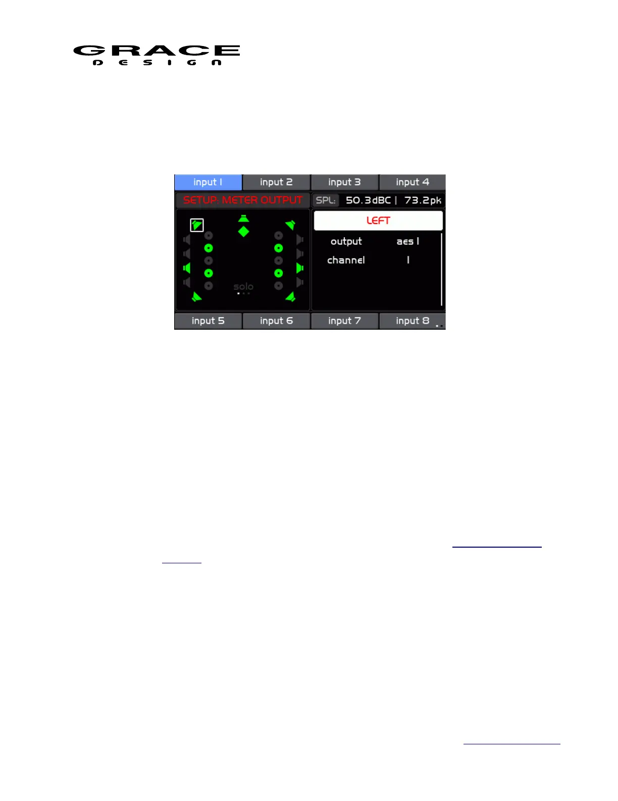
The Meter Output Setup screen is where the meter source signals are routed to physical output
connectors.
The left side of the screen window shows all of the available signals enabled in the current
Workflow. Speaker Icons that are green are enabled for the meter output. Speakers that are
disabled are gray. The currently selected channel has a white box around it.
On the right side of this screen there is a list of options and the top item is highlighted initially:
◦ channel name The name of the currently currently selected channel in the left
window. Pushing the VOLUME encoder enters the Channel Select mode. Turning
the encoder scrolls through the available channels. Pushing the VOLUME
encoder selects the highlighted channel for routing. See the Standard Channel
Routing section of this manual for details on channel routing.
◦ output Selects the meter output connector for the currently selected speaker.
Select "disabled" if the selected channel is not used in the meter output. The
selected speaker icon will turn gray.
◦ channel Select the desired connector channel for the currently selected DSP
channel. Select "disabled" if the selected channel is not used in the meter output.
The selected speaker icon will turn gray.
NOTE: If the selected meter output connector channel is already in use for CUE or Control
Room speaker signals a dialog box will appear asking if you want to replace the existing routing
Page 100 of 135 Table Of Contents