m908 User Manual, Rev. G
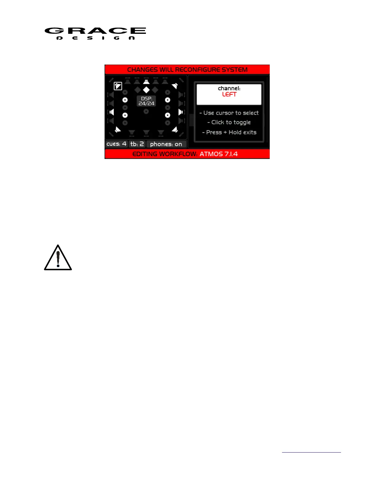
In the channel setup screen the VOLUME encoder controls a highlight cursor that can be
moved from speaker to speaker through all of the possible speaker positions. When a speaker is
highlighted push the VOLUME encoder to enable/disable that speaker position. When the
speaker is enabled it will be white. When the speaker is disabled it will be gray. The name of the
currently selected speaker will be shown in the right hand window.
It is highly recommended that channels L, C, and R always be enabled in any
workflow. Failure to have these three speakers enabled can lead to unpredictable
behavior of the MONO/L-R functions.
The small window in the middle of the speaker icons shows the current tally of DSP channel
utilization. It will update with the number of DSP channels allocated as you add or subtract
speakers. Continue scrolling through all of the speakers to get to the cue, talkback, and
headphones setup. When one of these switches is highlighted pushing the VOLUME encoder will
toggle through the following options:
• cues: Each push of the encoder increases the number of stereo cue paths to a
maximum of 8 stereo cues. The number of cue channels is limited by the available DSP
channels. For example, if there are only 4 DSP channels available then pushing the
VOLUME encoder will toggle through cues:0, cues:1, and cues:2.
• tb: Each push of the VOLUME encoder toggles the talkback function on or off. The
talkback system require 2 DSP channels.
• phones: Each push of the VOLUME encoder toggles the headphone system on or off.
The headphone outputs require 2 available DSP channels. If phones are enabled the DAC
output channels that feed the CUE/EXT connector channels 7-8 are routed to the
headphone amplifiers. These channels will not be available for routing to Control Room
Page 58 of 135 Table Of Contents