m908 User Manual, Rev. G
GPIO configuration is accessed in the System Setup screen.
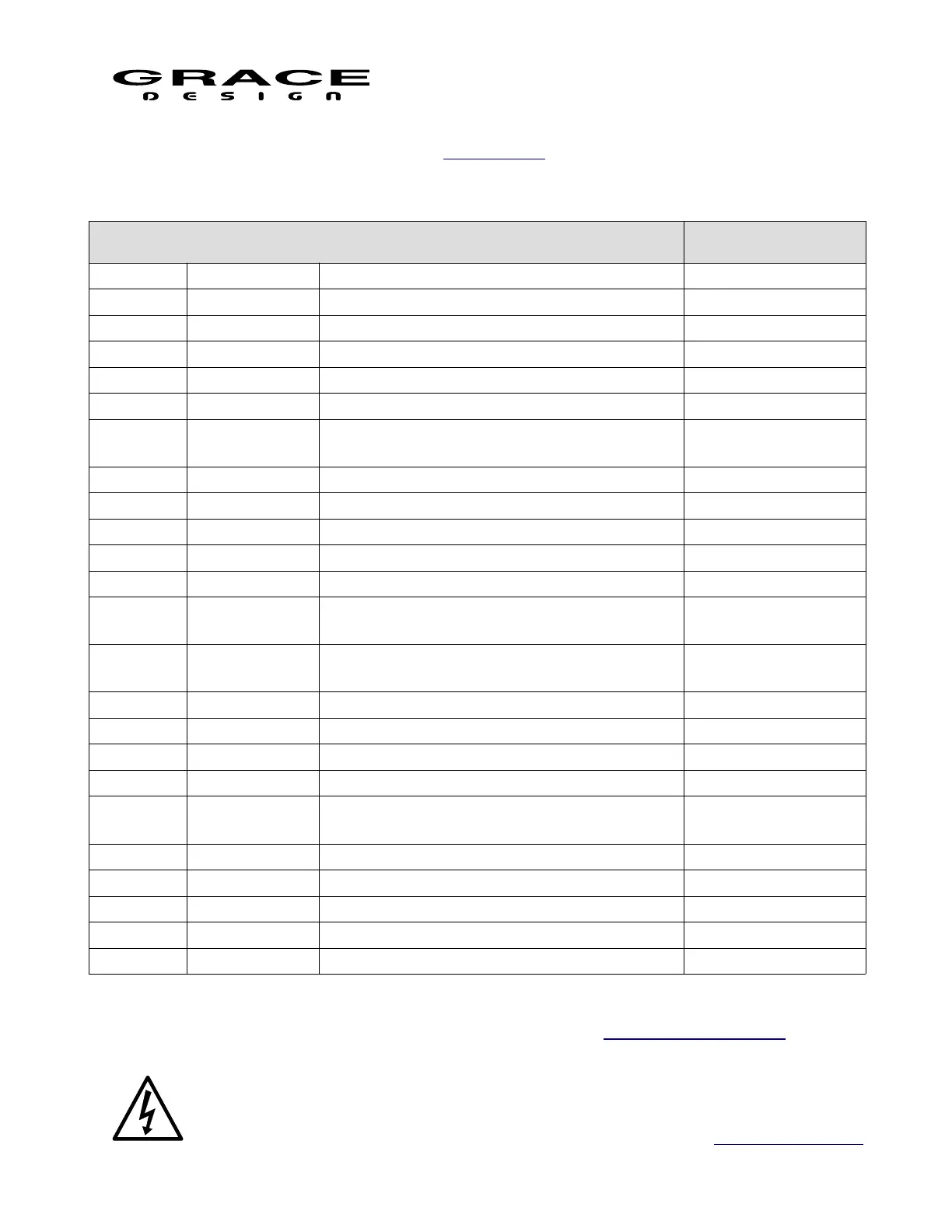
The table below contains the available input and output functions as well as the logic mode.
GPIO Functions
MODE FUNCTION Description Trigger
INPUT TALKBACK Activates TALKBACK logic level
INPUT User Switch A Activates User Switch A logic level
INPUT User Switch B Activates User Switch B logic level
INPUT User Switch C Activates User Switch C logic level
INPUT Input 1-16 Selects Monitoring Input 1-16 edge
INPUT
CR1-3 Selects Control Room Speaker System
CR1, CR2, or CR3
edge
INPUT MUTE Activates MUTE function logic level
INPUT DIM Activates DIM function logic level
INPUT MONO Activates MONO function logic level
INPUT L-R Activates L-R (left minus right) function logic level
INPUT MON>CUE Activates MON>CUE function logic level
OUTPUT
TALKBACK
RCU
TALKBACK RCU tally
OUTPUT
TALKBACK
EXT
TALKBACK EXT tally
OUTPUT User Switch A User Switch A tally
OUTPUT User Switch B User Switch B tally
OUTPUT User Switch C User Switch C tally
OUTPUT Input 1-16 Monitoring Input 1-16 tally
OUTPUT
CR1, CR2,
CR3
Control Room Speaker System CR1, CR2,
or CR3 tally
OUTPUT MUTE MUTE function tally
OUTPUT DIM DIM function tally
OUTPUT MONO MONO function tally
OUTPUT L-R L-R (left minus right) function tally
OUTPUT MON>CUE MON>CUE function tally
The table and illustration below indicates the locations of each GPIO pin and the circuit board
jumper for selecting the logic level for each pin. See the m908 Electrical Specifications to make
sure the GPIO electrical characteristics are compatible with your external equipment.
Before adjusting the GPIO pcb jumpers turn of the power at the PSU and remove
Page 106 of 135 Table Of Contents