m908 User Manual, Rev. G
14 Illustrations Index
Illustration 1: Audio and Clock Flow Diagram............7
Illustration 2: Audio Processing Flow Diagram...........8
Illustration 3: ACU Front Panel...................................8
Illustration 4: ACU Rear Panel....................................9
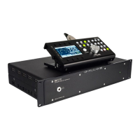
Illustration 5: RCU Front Panel.................................12
Illustration 6: RCU Rear Panel..................................13
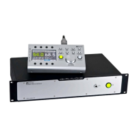
Illustration 7: PSU Front Panel..................................14
Illustration 8: PSU Rear Panel...................................15
Illustration 9: m908 System Load Splash Screen......20
Illustration 10: Home Screen.....................................21
Illustration 11: Input Page Select...............................24
Illustration 12: Input Summing Mode.......................24
Illustration 13: Input Summing Error: clocksource
mismatch....................................................................25
Illustration 14: Input Summing Error: sample rate
mismatch....................................................................25
Illustration 15: Input Summing Error: sync delay
mismatch....................................................................26
Illustration 16: Input Summing Error: ADC1 1-2 bal-
unbal...........................................................................26
Illustration 17: Direct Input Offset on active Input....27
Illustration 18: Direct Input Offset on inactive Input.27
Illustration 19: Direct Input Offset on Summed Input
...................................................................................28
Illustration 20: Headphone Crossfeed Flow Diagram29
Illustration 21: Headphone Crossfeed Response Plot 30
Illustration 22: Bass Management Flow Diagram.....33
Illustration 23: Cue Input Mute Indication................35
Illustration 24: Talkback-Cue Flow Diagram............36
Illustration 25: Solo/Mute Page Keys........................38
Illustration 26: Meter Output Routing.......................40
Illustration 27: Downmix Template Speaker Layouts43
Illustration 28: Headphone Source Select..................46
Illustration 29: Word Clock Flow Diagram...............50
Illustration 30: ACU Temperature Error....................51
Illustration 31: PSU Error..........................................51
Illustration 32: Communication Error.......................52
Illustration 33: Cooling Fan Error.............................52
Illustration 34: Workflow Setup Flowchart...............53
Illustration 35: Main Workflow Setup Screen...........54
Illustration 36: Select Workflow to Edit Screen........55
Illustration 37: Editing Workflow Screen..................56
Illustration 38: Workflow Channel Setup Screen.......58
Illustration 39: Editing Workflow Rename Conflict. .59
Illustration 40: Save System Workflow Changes
Dialog.........................................................................60
Illustration 41: Save Active System Workflow
Changes Dialog..........................................................60
Illustration 42: System Configuration Updating........61
Illustration 43: Cancel System Workflow Changes
Dialog.........................................................................61
Illustration 44: Selected Workflow to Load Screen...62
Illustration 45: Load System Workflow Dialog.........62
Illustration 46: Select Workflow to Copy Screen......63
Illustration 47: Select Template for new Workflow...64
Illustration 48: New System Workflow Confirmation
...................................................................................64
Click NO to return to the Select Template for New
Workflow screen........................................................64
Illustration 49: Select Workflow to Import from USB
...................................................................................66
Illustration 50: Import Workflow from USB Dialog..66
Illustration 51: Import Workflow from USB Status...67
Illustration 52: Import Workflow from USB Error
Dialog.........................................................................67
Illustration 53: Export Workflow to USB..................68
Illustration 54: Export Workflow to USB Confirmation
...................................................................................68
Illustration 55: Export Workflow to USB Status.......69
Illustration 56: Insert Proper USB Drive Message....69
Illustration 57: Export Workflow to USB Error.........70
Illustration 58: Select Workflow to Delete................70
Illustration 59: Delete Workflow Confirmation.........71
Illustration 60: Cannot Delete Active Workflow.......71
Illustration 61: Initial Setup Mode Dialog.................72
Illustration 62: Exit Setup Without Saving Dialog....72
Illustration 63: Edit Screen With Parameter
Highlighted but Not Selected for Editing...................73
Illustration 64: Edit Screen with Parameter
Highlighted and Selected for Editing.........................74
Illustration 65: Name Edit Screen.............................74
Illustration 66: Number Edit Screen..........................75
Illustration 67: Name Edit Navigation Keys..............76
Page 132 of 135 Table Of Contents