m908 User Manual, Rev. G
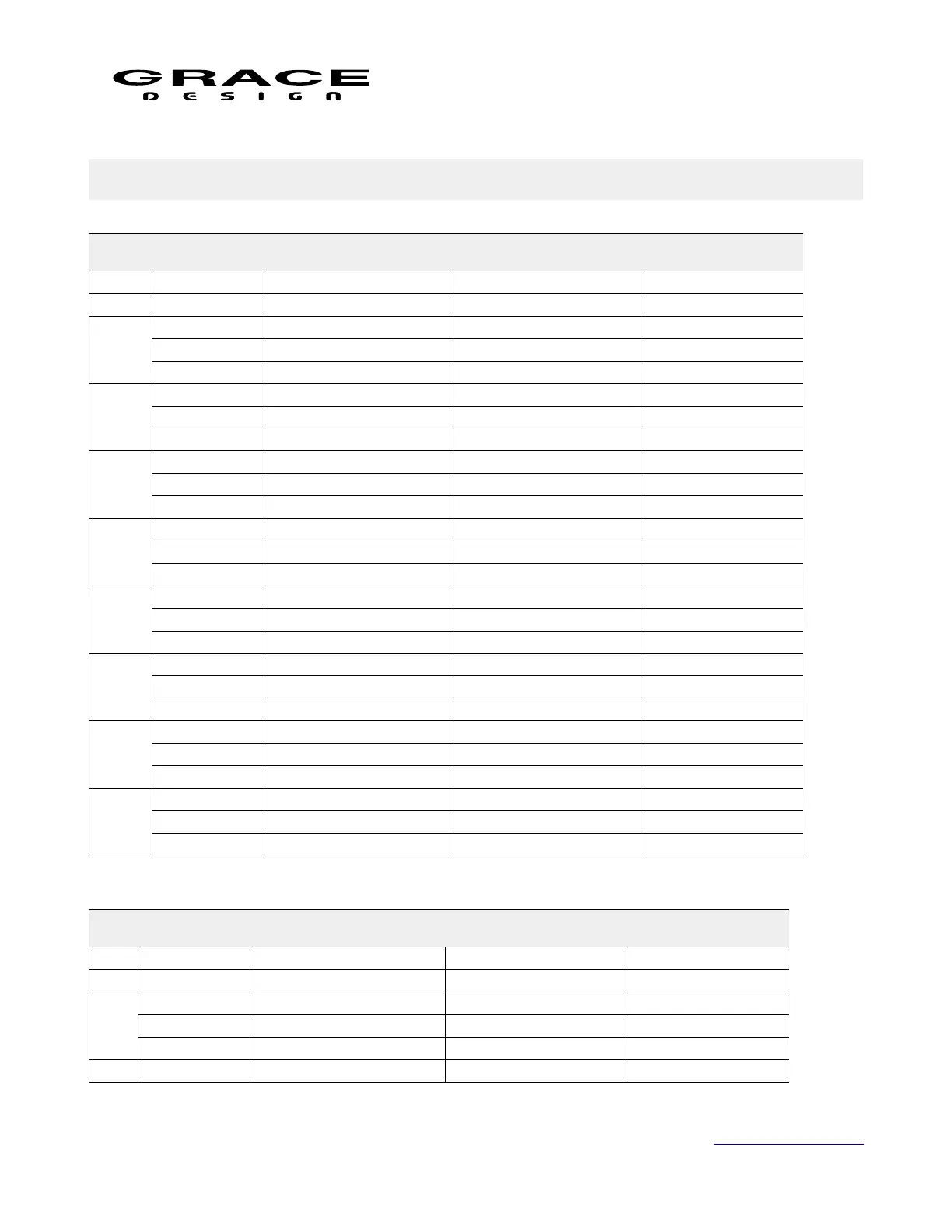
12 Cable and Connector Diagrams
DB25 Digital AES3 (Tascam Pinout)
CH# DB25 Pin# AES3 1 IN/OUT AES3 2 IN/OUT AES3 3 IN/OUT
13 GPIO 1 GPIO 2 GPIO 3
IN
1-2
25 GND GND GND
24 Positive(+) Positive(+) Positive(+)
12 Negative(-) Negative(-) Negative(-)
IN
3-4
11 GND GND GND
10 Positive(+) Positive(+) Positive(+)
23 Negative(-) Negative(-) Negative(-)
IN
5-6
22 GND GND GND
21 Positive(+) Positive(+) Positive(+)
9 Negative(-) Negative(-) Negative(-)
IN
7-8
8 GND GND GND
7 Positive(+) Positive(+) Positive(+)
20 Negative(-) Negative(-) Negative(-)
OUT
1-2
19 GND GND GND
18 Positive(+) Positive(+) Positive(+)
6 Negative(-) Negative(-) Negative(-)
OUT
3-4
5 GND GND GND
4 Positive(+) Positive(+) Positive(+)
17 Negative(-) Negative(-) Negative(-)
OUT
5-6
16 GND GND GND
15 Positive(+) Positive(+) Positive(+)
3 Negative(-) Negative(-) Negative(-)
OUT
7-8
2 GND GND GND
1 Positive(+) Positive(+) Positive(+)
14 Negative(-) Negative(-) Negative(-)
DB25 Analog (Tascam Pinout)
CH# DB25 Pin# CR Out 1, CR Out 2 CUE/CR EXT. ADC In (option)
13 Not Connected Talkback Out +3.3V Not Connected
1
25 GND GND GND
24 Positive(+) Positive(+) Positive(+)
12 Negative(-) Negative(-) Negative(-)
2 11 GND GND GND
Page 127 of 135 Table Of Contents