m908 User Manual, Rev. G
9. L, C, R, LS, SUB, LR, LB, RB: Speaker select for SOLO or MUTE. See SOLO MUTE for
details.
10. SOLO/MUTE: Selects between SOLO and MUTE monitoring mode. See SOLO MUTE for
details.
11. A, B, C: User programmable switches. See A B C User Switches operation for details.
12. VOLUME: Monitor level control for Control Room speakers and headphones. See VOLUME
operation for details.
13. TALKBACK: Talkback is activated by pushing this switch. See TALKBACK operation for
details.
14. INPUT Select switch and Input Page change. See Input Select operation for details.
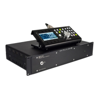
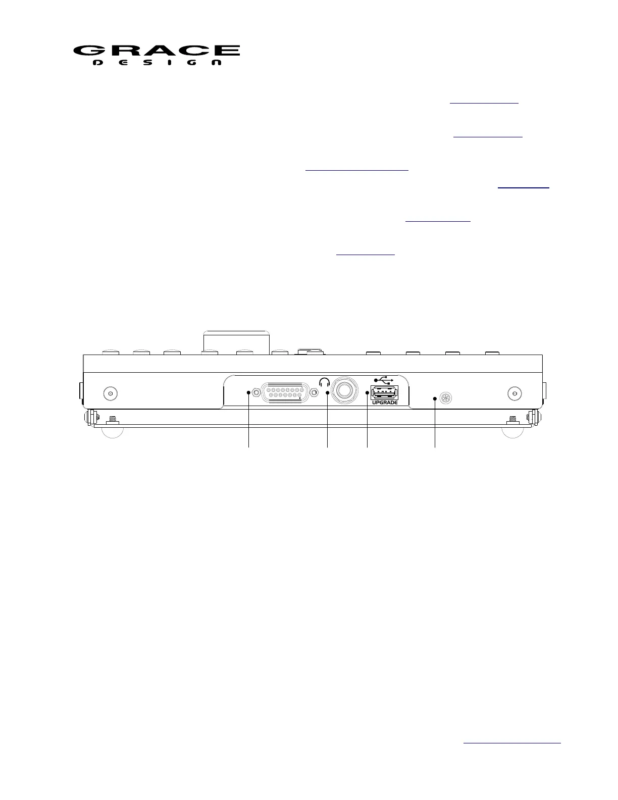
3.7 RCU Rear Panel Connections
1. m908 ACU DB15: Serial control cable connection to ACU
2. Headphone Jack 1/4" TRS: Carries stereo headphone signal from ACU headphone amplifiers.
This jack is wired in parallel with ACU front panel headphone jack.
3. USB Host USB-A: USB host connection for user workflow export/import.
4. Microphone: Built in mic for talkback and spl measurement
3.8 RCU Tilting Base
The RCU features a tilting base so that it can be tilted to an angle for optimal viewing. Loosen
the four thumbscrews located on each side of the RCU and tilt the unit to the desired angle.
While holding the RCU at this angle tighten the four thumbscrews. The tilt range is from
Page 13 of 135 Table Of Contents