EasyManuals Logo

GW Instek PSW Series User Manual

GW Instek PSW Series
184 pages
To Next Page IconTo Next Page
To Previous Page IconTo Previous Page
Page #65 background imageLoading...
Page #65 background image
OPERATION
65
8. Use the Voltage knob to set the
voltage limit (crossover point).
Voltage
9. Use the Current knob to set the
current.
Current
Note
Notice the Set key becomes illuminated when
setting the current or voltage. If the Voltage or
Current knobs are unresponsive, press the Set key
first.
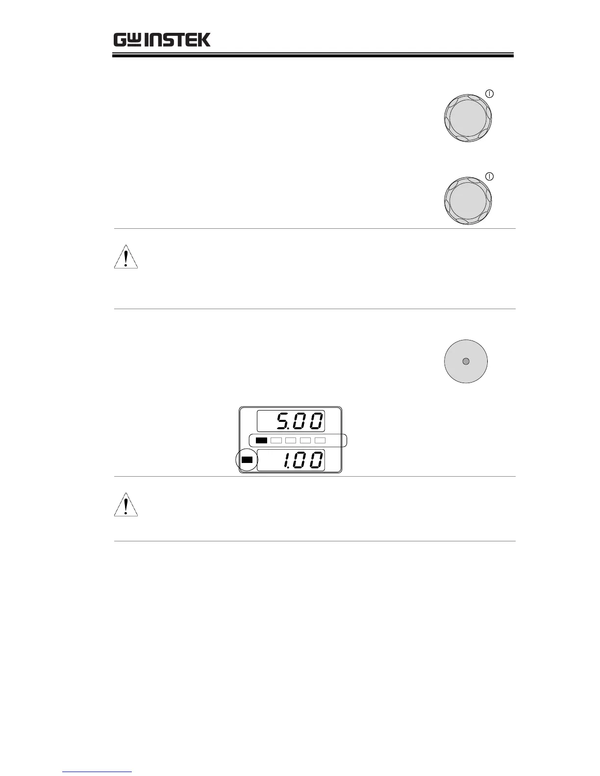
10. Press the Output key. The Output
key becomes illuminated.
Output
% W
V
A
C C
% W
20 40 60 80 100
CC and the Power Bar
will become illuminated
(bottom left & center)
Note
Only the current level can be altered when the
output is on. The voltage level can only be changed
by pressing the Set key.
For more information on the Normal Function
Settings (F-00 ~ F-61, F-88~F-89) see page 102.

Table of Contents

Other manuals for GW Instek PSW Series

Questions and Answers:

Question and Answer IconNeed help?

Do you have a question about the GW Instek PSW Series and is the answer not in the manual?

GW Instek PSW Series Specifications

General IconGeneral
Ripple & Noise (CC)≤ 3mArms
ProtectionsOVP, OCP, OTP
Remote SenseYes
ProgrammableYes
Operating Temperature0°C to 40°C
Storage Temperature-20°C to 70°C
Voltage Resolution1mV
Current Resolution1mA
Current Accuracy±0.1% + 10mA
Ripple & Noise (CV)≤1mVrms
Load Regulation (CC)≤0.1% + 5mA
Line Regulation (CC)≤0.1% + 5mA
Remote InterfaceUSB, RS232
DisplayLCD

Related product manuals