31
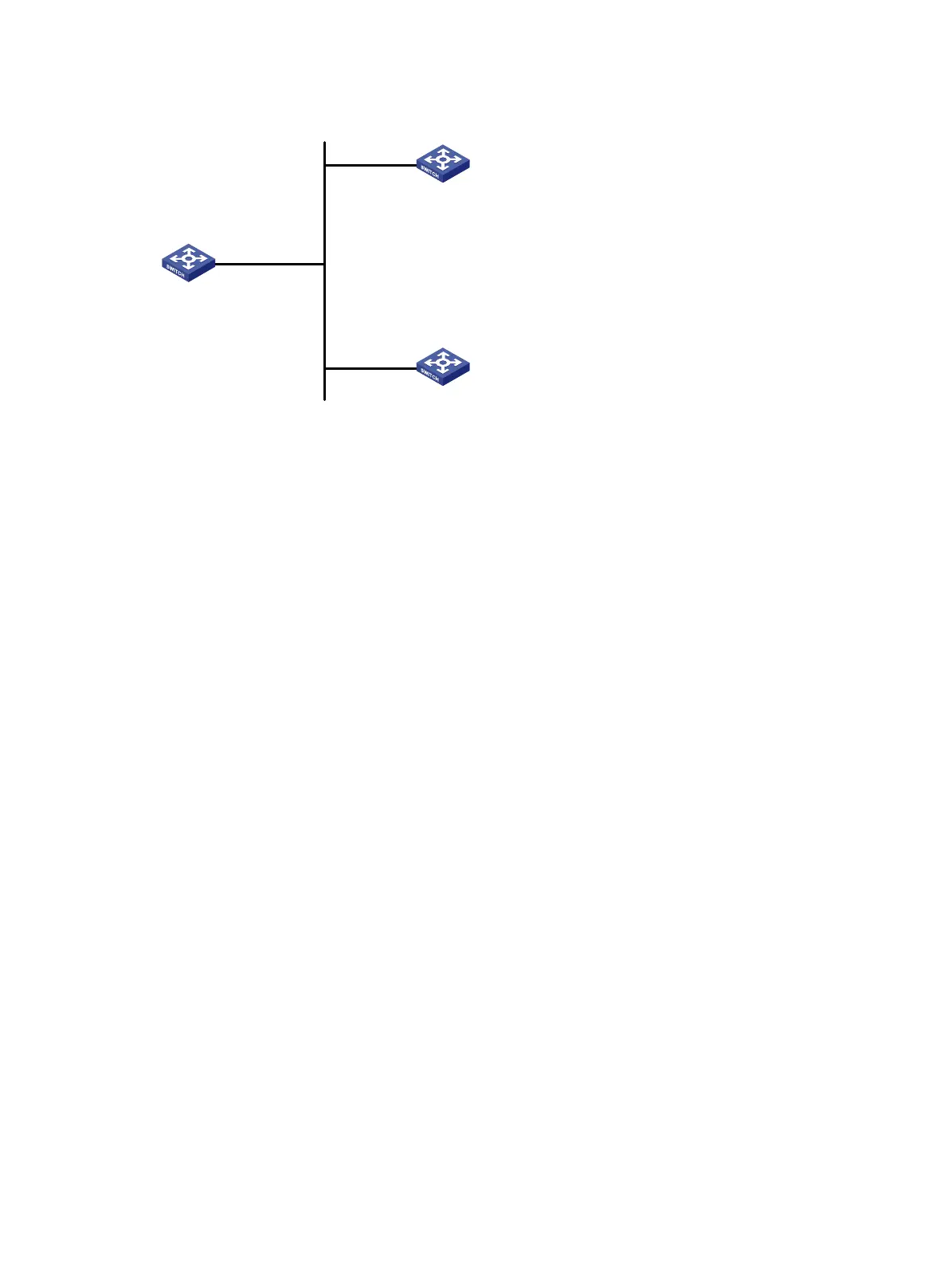
Figure 16 Network diagram
Vlan-int2
3.0.1.31/24
Vlan-int2
3.0.1.32/24
Vlan-int2
3.0.1.30/24
Device A
Device C
Device B
Configuration procedure
1. Set the IP address for each interface as shown in Figure 16. (Details not shown)
2. Configure Device A:
# # Configure the Device A to work in the NTP broadcast client mode and receive NTP broadcast
messages on VLAN-interface 2.
<DeviceA> system-view
[DeviceA] interface vlan-interface 2
[DeviceA-Vlan-interface2] ntp-service broadcast-client
3. Configure Device B:
# Enable NTP authentication on Device B. Configure an NTP authentication key, with the key ID of 88
and key value of 123456. Specify the key as a trusted key.
<DeviceB> system-view
[DeviceB] ntp-service authentication enable
[DeviceB] ntp-service authentication-keyid 88 authentication-mode md5 123456
[DeviceB] ntp-service reliable authentication-keyid 88
# Configure Device B to work in broadcast client mode and receive NTP broadcast messages on
VLAN-interface 2.
[DeviceB] interface vlan-interface 2
[DeviceB-Vlan-interface2] ntp-service broadcast-client
4. Configure Device C:
# Configure Device C to work in the NTP broadcast server mode and use VLAN-interface 2 to send NTP
broadcast packets.
[DeviceC] interface vlan-interface 2
[DeviceC-Vlan-interface2] ntp-service broadcast-server
[DeviceC-Vlan-interface2] quit
# Device A synchronizes its local clock based on the received broadcast messages sent from Device C.
View NTP service status information on Device A, you can see that Device A has been synchronized to
Device C, and the clock stratum level of Device A is 4, while that of Device C is 3.
[DeviceA-Vlan-interface2] display ntp-service status
Clock status: synchronized
Clock stratum: 4