CW:SET:PHASE 90
CW:SET:PHASE?
90.000
CW:SET:TRANS_PHASE OFF
CW:SET:TRANS_PHASE?
OFF
CW:SET:TRANS_POL OFF
CW:SET:TRANS_POL?
OFF
This commands will be send to AXOS and test can be performed in accordance to it.
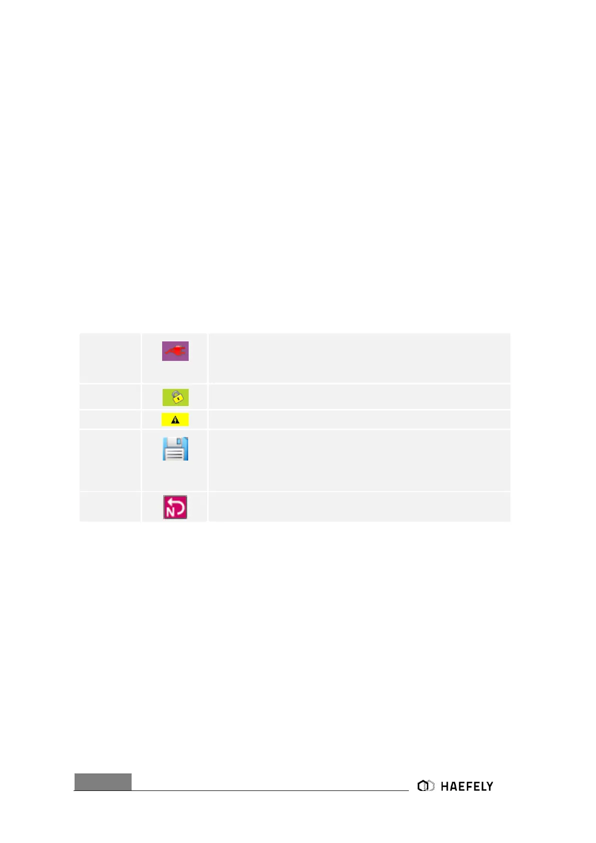
6.3.3 Icon bar
The Table presents a overview of icons in the operating menu. The icons get displayed in the
right upper corner of the operating menu, except position 3.
When button “line” pushed in the operating menu, connection between
“EUT supply inputs (L, N, PE)” and “EUT supply output (L, N, PE)” is
existing; note: no actual “EUT
Supply Input” required for the connection
When circuit closed between PIN 5 and PIN 4 in Table 5-3, either
through existing factory bridge or external circuit connection
When generator charging, symbol gets displayed at touch screen
“Reporting data symbol”, when pushing “Rep.Data” button, this floppy icon
comes up in
the right upper corner of the window and the report of the test will be
saved via USB- port on a connected device; Note: only accessible
when test has finished
Symbol, when L and N on “EUT Supply Input” are exchanged, therefore,
L and N must be changed back
6.4 Test Report Data
Test report data can be automatically saved to USB memory stick. If "Report Data Saving:
Automatic" is selected in the "Setup" menu, test data are saved automatically after each test. If
"Report Data Saving: Manual" is selected, test data can be saved on the memory stick by using
the "REPORT" key within the accordingly menu.
The test data are saved into five CSV files which can easily imported into Excel or similar
applications. Data are saved as follows:
Prg_Log.csv : Test coclusion
Prg_Set_Seq.csv : Test header data
PrgItem002_Log.csv : Test log data
PrgItem002_Set.csv : Test setup data
 Loading...