12.3 Dips
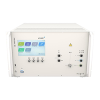
To create the Voltage dips an external transformer is necessary, because a second voltage level
is required. When purchasing the DIP 116 from the HAEFELY AG the position 5 at the rear view
graphic can be used. The Figure 12-2: DIP 116 Transformer connected gets displayed when DIP
116 is successfully connected. Exact hardware configuration of DIP 116 is described in capture
11.3.1. Fully compatibility is guaranteed with the AXOS
5
.
Figure 12-2: DIP 116 Transformer connected
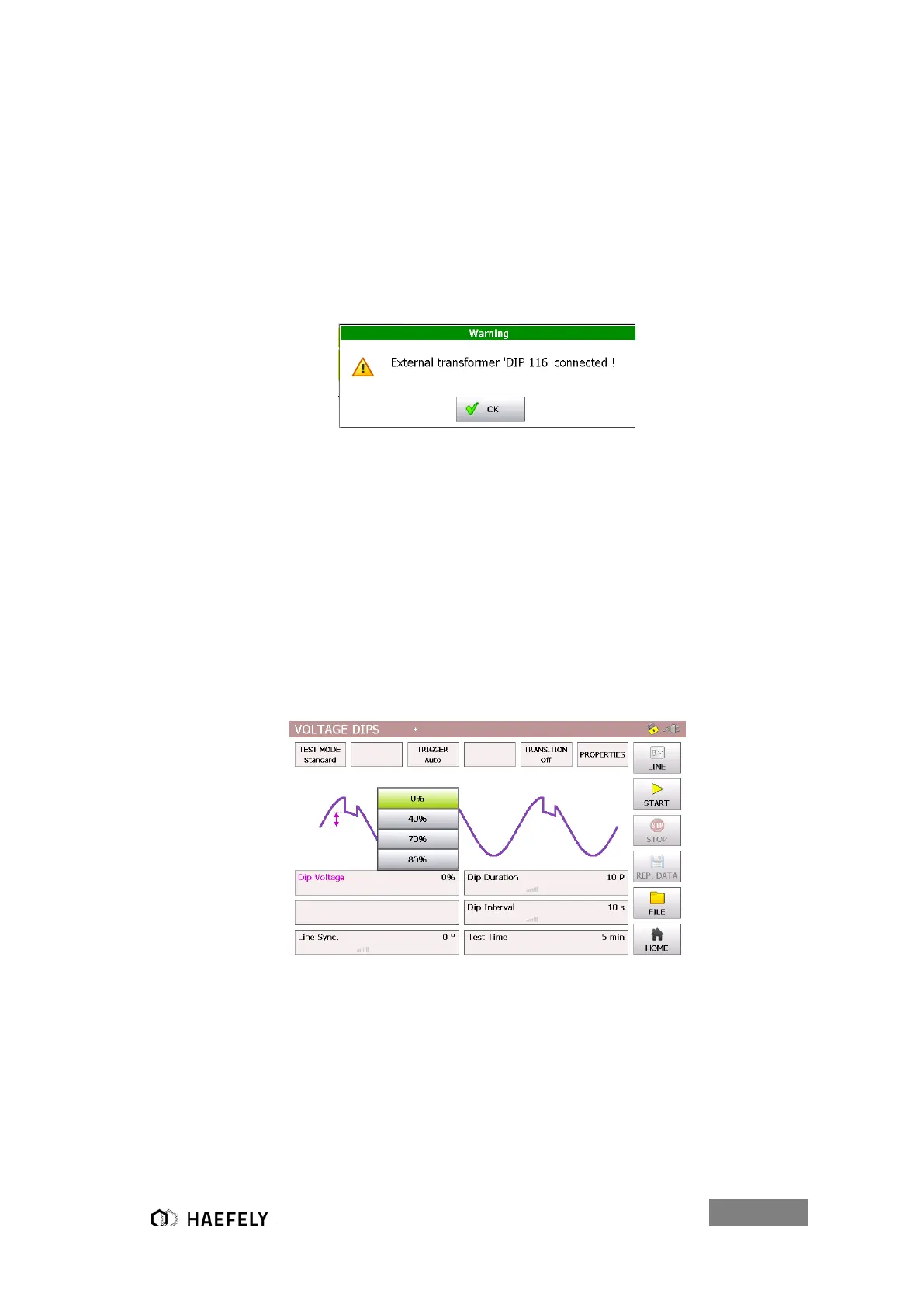
Only in this case the V dip voltage can be proportionally controlled regarding to the U1 nominal
voltage via the touch screen or via remote software. Moreover all other adjustments are
compatible with the AXOS
8
. Reference voltage according to the U1 nominal can be selected. V
dip can either be 0%, 40%, 70% or 80% in reference to U1 nominal, when using the D116
transformer. The selection happens in the “Dip Voltage” menu field. When selecting 0% it creates
a voltage interrupt, since the V dip becomes 0V.
The Figure 12-3: Voltage Dips Standard mode shows the voltage dips in standard mode. When
pushing the particular function name: “Dip Voltage”, “Line sync.”, “duration”, “interval” and “test
time a visual description gets open with a purple bow as seen below. For changing the parameter
the value has to be pushed, for instance 5 min. New parameter can be entered. When pushing
the button “file” data can be saved and loaded.
Figure 12-3: Voltage Dips Standard mode
The Figure 12-4: Voltage Dips pre-compliance mode (External transformer)represents the pre-
compliance mode of the “voltage dips” menu. The purple bows define the function and show which
particular parameter influenced the function. All parameters can be adjusted, when test is
operating.
 Loading...