12 Voltage dips &
interrupts
12.1 General information
For the voltage dips & interrupts only the EUT will be connected via the line outputs (L, N, PE) in
the front view. The EUT Supply Input (L, N, PE) in the rear view gets connected to the power
supply. For verification of the signal, Pos.4 and Pos.5 in Figure 5-1 can be connected to the
oscilloscope. Further adjustments of the operation menu will be described in the following under
captures.
12.2 Interrupts
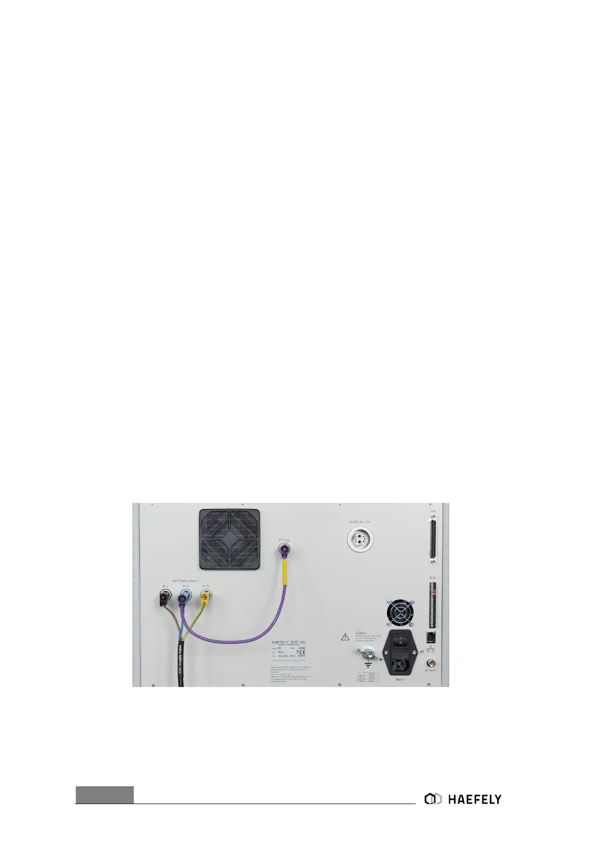
Only the voltage interrupts it is possible to create without an external transformer. To create those
interrupts there must be a connection between V dip and N via the purple banana plug, as seen
in Figure 11-1. Additionally, it has to be connected to an external powers supply source.
Afterwards it can be selected between pre-compliance mode and standard operating menu. The
entering of “duration”, “interval”, “test time”, “synchronization” via touch screen by pressing each
specific function (Figure 11-3). When pushing the function name a purple bow opens up and
defines the parameter in the graphic. After successfully selecting the key parameter, the “start”
button can be pushed and the parameter gets applied.
Figure 12-1: Voltage interrupts electrical installation
 Loading...