Voltage dips & interrupts
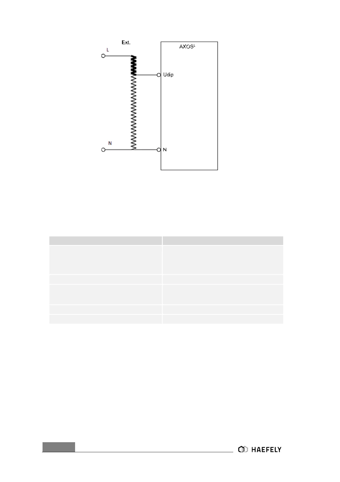
Figure 12-6: External transformer
Now the incoming V dip can be regulated directly at the transformer. Note: No further connection
of the link data cable at the rear view possible.
12.3.3 Properties
External condition (e.g. device or PLC
signal), the position becomes 1 and causes
an action (Ignore,
Alarm, Test Stop or test stop & line off)
Limits the current (L, N, PE front view) to the EUT.
Action: Ignore, Alarm, Test stop, Test stop &
line off
Due to EUT fails, AXOS
8
cause an action
which can be: Ignore, Alarm, Test Stop, Test
Stop & Line off.
Voltage locked at L, N, PE when test has finished
Acoustic signal when test ends
12.3.4 Transition
The Figure 12-7: Voltage Dips Transition shows the “transition” menu. It is possible to select
independently “Duration”, “Interval”, “Phase” and “Alternate polarity”. To be able to select “phase”
the Synchrony has to be either set as Synchronization or external Synchronization, otherwise it
is not possible to access it. Eventually, every parameter can be changed by pushing the certain
value.
 Loading...