10.1.2 Short Circuit Current (SCC) Telecom Wave
Figure 10-2: Short Circuit Current (SCC) Telecom Wave
Front time: Tf = 1,25 x Tr = 5 µs ± 20%
Time to half value: Td = Tw = 320 µs ± 20%
10.1.3 TW 8 module
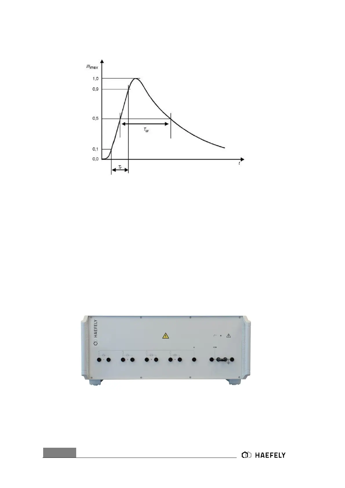
When external TW 8 (Figure 10-3: Telecom Wave module) module is connected it gets
automatically indicated via the link cable (intelligent input). In the front view are three different
coupling impedances (1 x 15 Ohm (HI-COM), 4 x 40 Ohm, 4 x 40 Ohm gas arresters) options.
The user selects on the coupling unit (TW8 module) which impedance is required for the particular
application. In the block diagram (Figure 9-8) the exact outputs are defined in accordance to the
standard.
Figure 10-3: Telecom Wave module
On the right hand side there is a black bridge. There I can select if I want to have the output to
the EUT either floating or not.
For instance:
 Loading...