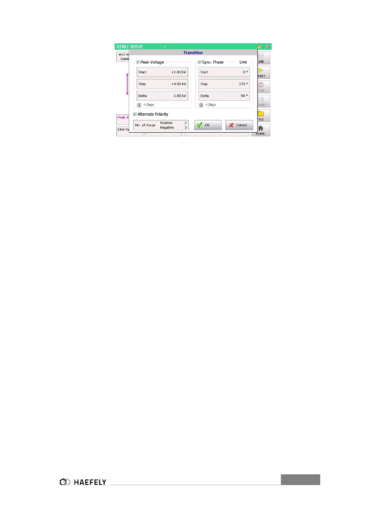
Figure 9-7: Ring Wave transition mode
After successfully entering the parameter, “OK” button can be pushed and then the “Start” button
in the main menu. Test should be proceeding now.
9.1.5 Trigger
In the trigger window it is possible to select between “auto”, “manual” or “external trigger”. When
being in “manual mode” the user controls the trigger by pressing the start button first, after the
generator is charged the menu button “trigger” flashes up and can be pushed. “Auto mode”
provides the signal according to set up and works completely automatically. All key parameter
like “peak voltage” sets the user through the touch screen in the main operating window. In
“external trigger” the signal for the trigger comes from an external source and gets connected via
PIN 11 in the AUX input at the rear view of the AXOS
8
.
9.1.6 Synchronization AC
To synchronize the ring wave signal with the main supply source it is necessary to adjust in the
menu “Synchronization” and then “Line Sync.”. Further adjustments of the angle can be done in
a range from 0°to 359°. However, if no power supply is connected to the EUT input at the rear
view, it has to be entered “Async.”, otherwise it is impossible to get a Surge impulse of the
generator.
In external synchronization, the output with the position 8 Figure 5-2 in the rear view is in use. As
an external source could be used for instance a manual CDN. Normal operation through the touch
screen is possible.
9.1.7 Output & Coupling Paths
In the output&coupling options (Figure 9-8: ANSI Output & Coupling Paths Ring Wave) can be
automatically selected between the manual FP SURGE 100M2, direct output and line output.
Similar outputs are used as for SURGE combintaion wave application, simply with different
characteristics of generator. Detailed information about the output are explained for the front view
in Figure 5-1. The automatic 3 phase CDN FP COMB 32 gets indicated automatically when
connected, similar to DIP 116 or TW8 module. The coupling is in accordance to the IEC standard
(Figure 9-9: Figure 8-8 IEC Output & Coupling Paths). Additionally, coupling between LN-PE and
 Loading...