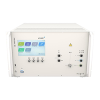
For instance, in the Standard Mode after selecting the peak voltage field, the numeric display
appears as shown in Figure 6-5. In a similar way works the repetition rate and the number of
surge. Awareness is to give for line synchronization; hence, it has been described more detailed
in the capture 6.3.4.
Figure 7-5: Surge peak voltage
In Pre-Compliance Mode, the parameter values can be changed in set increments with the use
of arrow keys or by pressing the number between the arrow keys. Pressing the number between
the arrow keys will bring up the numeric display shown in Figure 7-5: Surge peak voltage.
Once the value is selected, the screen will return to the operation mode (standard or pre
compliance).
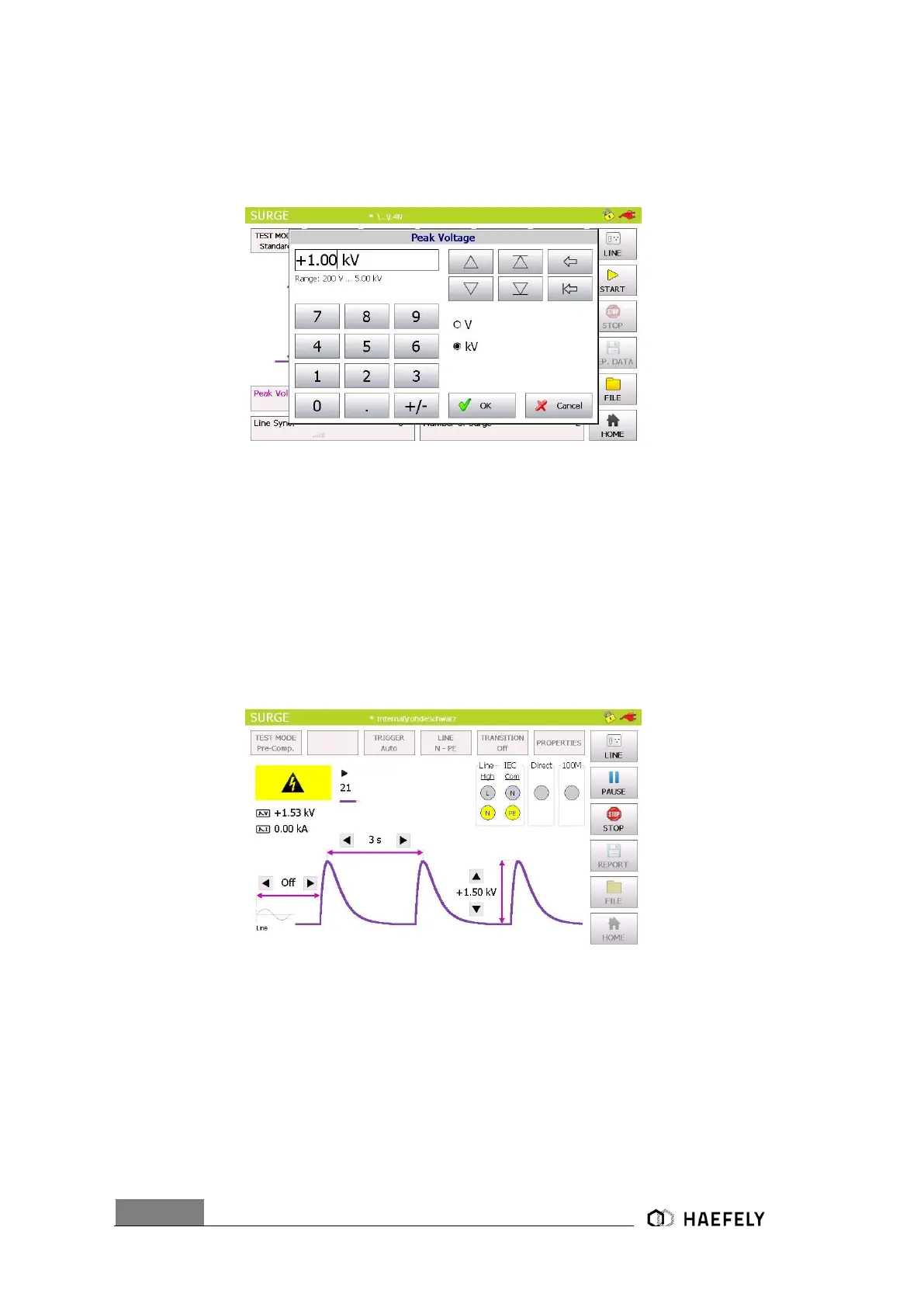
The user is able to see nominal values of the peak voltage, reputation time and the
synchronization period. Additionally, these values can be modified while the test is proceeding. It
happens by simply pressing each particular function. The test stops when pushing the “STOP”
button.
Figure 7-6: Surge Pre-compliance mode charging
In the right corner of the graphic is the plug flashing in red, when direct connection between L, N,
PE to the “EUT Supply Input” and button “line” has been pushed. The safety lock symbols shows
that the safety circuit has been closed between PIN 4 and PIN 5.
Information about Transition, Trigger and properties has to be entered independently if the test
has stopped. “Transition” and “Trigger” are only accessible in standard operating mode.
 Loading...