EB+ Gen3Installation guide
392013 Innovative Vehicle Solutions
3 º
3 º
3 º
3 º
Within LH & RH
chassis members
XY
Rear view
Plan View
5 º
5 º
5 º
5 º
Single or Tri-axle
Within LH & RH
chassis members
Tandem axle
XY
Trailer X Y
Semi 1.5 m 1.5 m
Centre-axle 1.5 m 1.5 m
Full 3.0 m 1.5 m
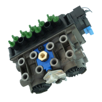
Chassis installation
The following installation parameters are required for
correct stability operation.
Roll angle : ± 3 ° (1:20)
Yaw angle : ± 5 °
The EB+ Gen3 system is to be mounted within distance
X & Y from the centre line of the rear axle group / bogie
(includes lift axles).
The EB+ Gen3 assembly to be within the main left hand
(LH) and right hand (RH) chassis members of the vehicle.
For any other applications please refer to Haldex
Technical Services.
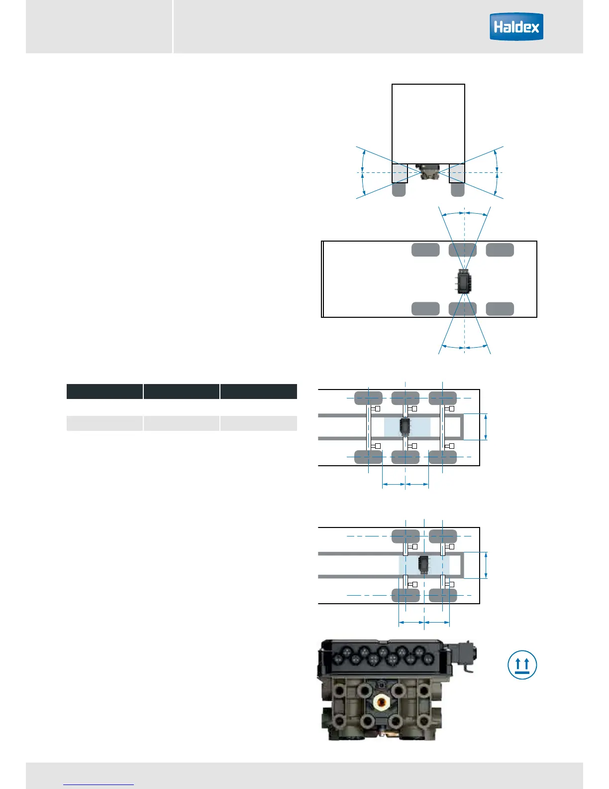
Pitch angle: assembly must be mounted vertically.
The assembly should not be in direct spray or splash
water area and should be protected against high
pressure cleaning.
Haldex recommended position for maximum stability
performance. Fitment of EB+ Gen3 outside of this area
may affect the stability performance.
This way up
Position of EB+ Gen3 assembly