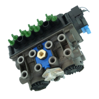
EB+ Gen3Installation guide
432013 Innovative Vehicle Solutions
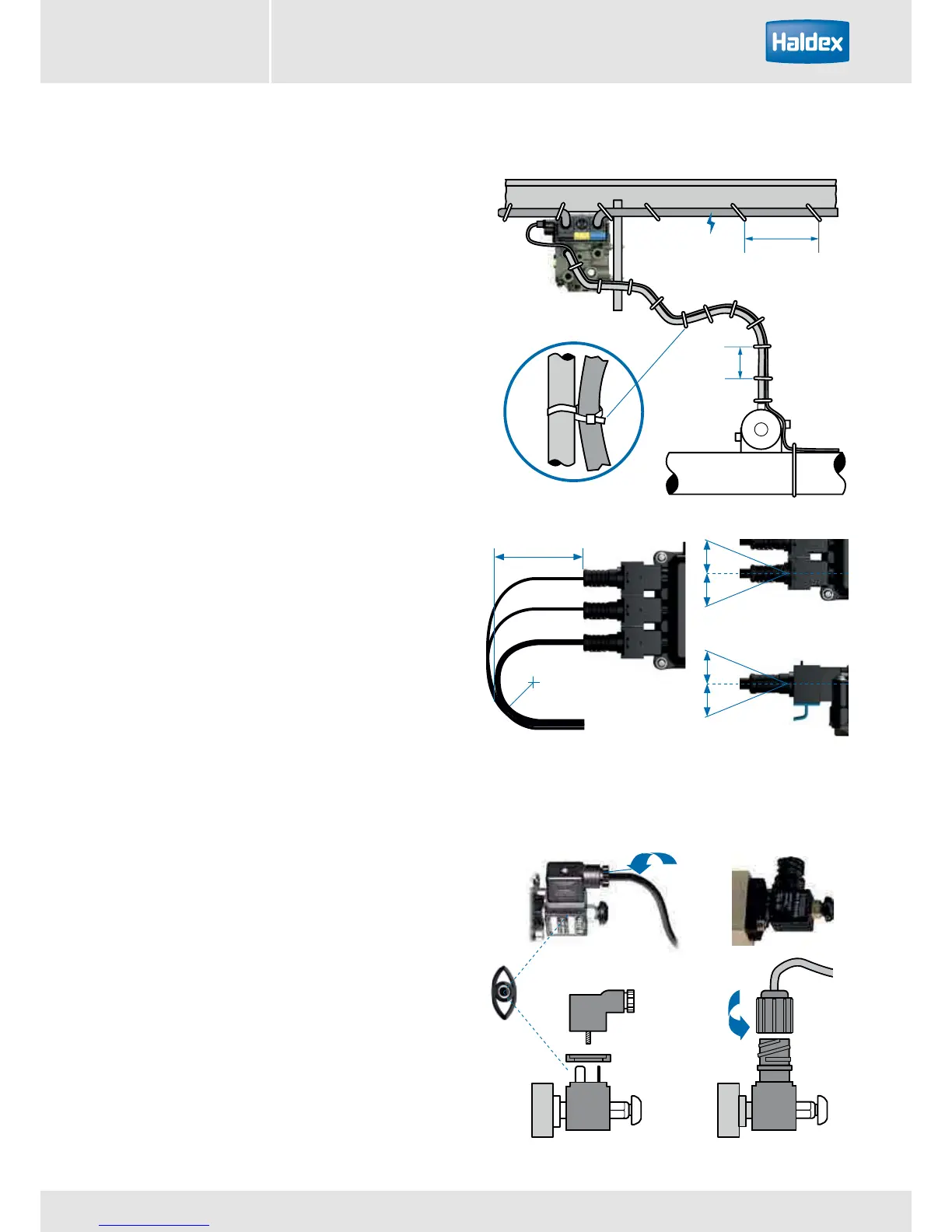
Cable tie
Axle
300 max
Deck of trailer
150 max
24v
0 mm
0 mm
Sensor / COLAS
®
/ ILAS
®
-E connection
Sensor cable route should follow the centre line or
outer radius of pipe or hose.
Tie wraps not to be over tightened because on brake
application rubber hose expands, i.e. tie could damage
the hose and sensor cable.
Do not run sensors leads in spiral wrapping on hoses.
Power leads should be secured down the chassis rail in
trunking or to piping and should be secured with
300 mm maximum intervals.
All cables should run ‘up to’ ECU connections.
The route of all of the cables from the connector
should not start to bend so that the connectors are
strained.
Allow distance of 120 mm (minimum) before bending
of cable.
Cable should be secured down the chassis rail to
existing piping and should be secured with 300 mm
maximum intervals or inside trunking.
Position rubber gasket ‘R’ in position shown.
Note:
All cables should run ‘up to’ connector.
120 mm min
0 mm
100 mm min
bend radius
0.5 - 0.6 Nm
(0.4 - 0.5 lbft)
4 - 6 Nm
(3 - 4.4 lbft)
DIN connector
R
R
0 mm
24 V