EB+ Gen3 Installation guide
82 Innovative Vehicle Solutions 2013
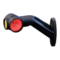
Super AUX
modify button
Super AUX option
is selected
Note colour
Super AUX (S AUX)
The Super AUX connection was developed as there are
a number of applications where trigger signals from
the truck and trailer are required.
Connections via Power B (black connector)
› 1 x 24N power supply (2 pins)
› 3 x inputs (i.e. A, B and C) and 24 V signal (4 pins)
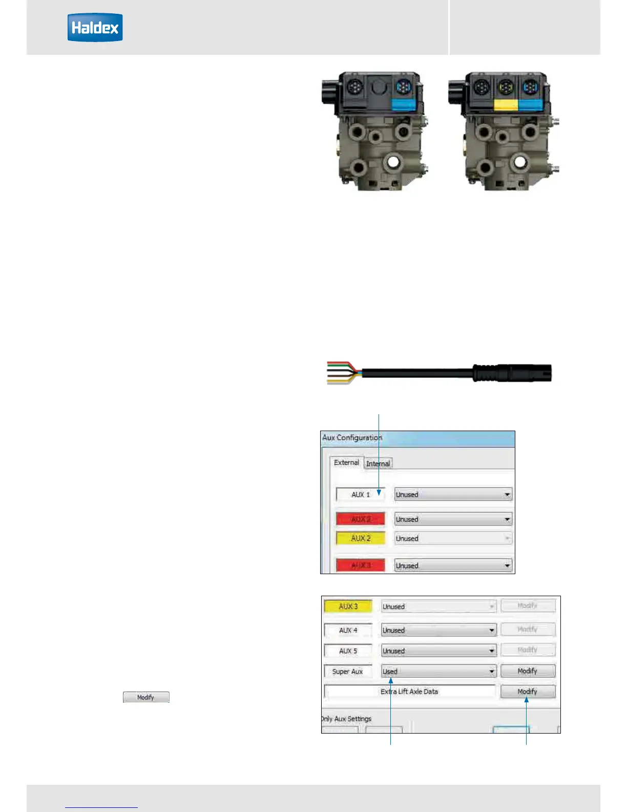
Auxiliary connection cables: to use the full auxiliary
functionality of “Super AUX”, the following cable can
be used.
814 002 3xx series
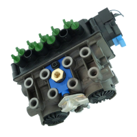
Already with EB+ Gen1 Haldex introduced a ‘Power B’ socket for backup power supply by stop light ISO 12098
/ ISO1185 (24N). This link to the lighting system has been extended by the introduction of the ‘Super AUX’. The
connector includes an additional three digital inputs and 24 V signal supply (only use the 24 V signal supply for
the Super AUX control switches). The control inputs can be linked to any auxiliary feature and this allows very
sophisticated applications to be realised in a very simple manner. Some examples for controllable auxiliary features
are ‘traction support’ and / or ‘steer axle lock’ and / or ‘EBD’ (=Electric Brake Demand). Backup power is always
available by default.
Programming Super AUX using DIAG+ V6
The "AUX configuration" screen shows the various
auxiliary connections that can be used.
AUX 1
AUX 2 Red only
AUX 3 Red only
AUX 4
AUX 5
Super AUX
Clicking on the drop down arrow displays a list of
options that can be selected on that auxiliary.
Conguring Super AUX
Click on the button to configure the Super
AUX inputs.