EB+ Gen3Installation guide
612013 Innovative Vehicle Solutions
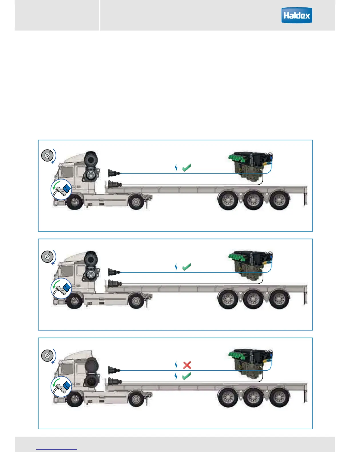
Fig 2
ISO7638 - 7 Pin
EBS
+EB
= Full EBS function
Fig 3
ISO7638 - 5 Pin
ABS
EB+
= ABS + ELS Function Only
No CAN data bus
Fig 4
ISO12098 / ISO1185 - (24N)
ABS/EBS
EB+
= On foot brake application
ABS function only
ISO 7638 7-pin
ISO 7638 5-pin
ISO 12098 / ISO 1185 (24N)
EBS
ABS
ABS / EBS
Fig 1
Fig 2
Fig 3
EB+
= full EBS function
EB+
= ABS + ELS function only
(no CAN data bus)
EB+
= on foot brake application
ABS function only
System layout
The system fitted to your trailer may have 2 or 4 sensors and 2 or 3 modulators (EPRV’s). The variants available
being 2S / 2M, 4S / 2M and 4S / 3M.The system can be powered by the following methods.
ISO 7638 7-pin - Full EBS function fig 1.
ISO 7638 5-pin (no CAN data bus) - ABS + ELS function only fig 2.
ISO 12098 / ISO 1185 (24N) - stop light powering provides ABS function fig 3.
Note:
The ISO 7638 controls a trailer warning device in the driver’s console.