12.1 Connecting to the External Control Terminals
218
To prevent electric shock accidents and damage to the equipment,
always observe the following precautions when making connec
-
tions to external terminal blocks and external connectors.
• Before making connections, turn off the power on the instrument
and the equipment to connect.
• Do not exceed the specified signal levels for signals supplied to
external terminal blocks.
• Ensure that devices and systems to be connected to the external
control terminals are properly isolated.
• The external control ground terminal is not isolated from the Memory
HiCorder’s chassis ground. Make certain that there will be no poten
-
tial difference between the external control ground terminal and the
ground of any connected device. Otherwise, the Memory HiCorder or
device could be damaged.
• To avoid electric shock, use the recommended wire type to connect to
the current input terminals, or otherwise ensure that the wire used has
sufficient current handling capacity and insulation.
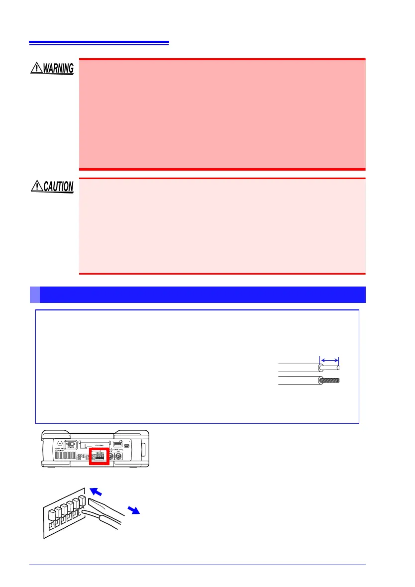
Terminal Connections
Required items:
Recommended cables:
single strand diameter 0.65 mm (AWG22),
multi-strand 0.32 mm
2
(AWG22)
Usable cables:
Single strand diameter 0.32 to 0.65 mm (AWG28 to 22),
Multi-strand 0.08 to 0.32 mm
2
(AWG28 to 22)
Strand diameter 0.12 mm or greater (per wire)
Standard insulation stripping length: 9 to 10 mm
Button operation specified tool: Flat-blade screwdriver
(shaft diameter 3 mm, tip width 2.6 mm)
Single strand
Multi-strand
10 mm
1 Press in the button of the terminal with a
flat-blade screw driver or other tool.
2 While the button is depressed, insert the
wire into the electric wire connection hole.
3 Release the button.
The electric wire is locked in place.
1
2
3
Right side
 Loading...