1
2
OK
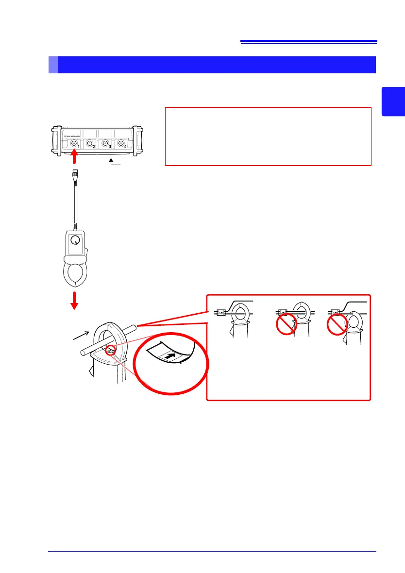
Attach the clamp around only one conduc-
tor. Single-phase (2-wire) or three-phase
(3-wire) cables clamped together will not
produce any reading.
The arrows on the clamp indicating the direction of current
flow should point toward the load side.
L
O
A
D
S
O
U
R
C
E
Conductor
The scaling function needs to be set according to the
clamp sensor model being used. Refer to "Converting
Measurement Values (Scaling Function)" (p. 97) for
details.
Clamp the sensor around the measurement object.
Top of instrument
Connect the BNC plug on the clamp sensor to the analog
input terminals (BNC jack) on the Memory HiCorder.
The connection method is the same as described for other Connection
Cables.
(Example: Model 9018-50 Clamp-on Probe)
Front
Current flow
direction arrow
 Loading...