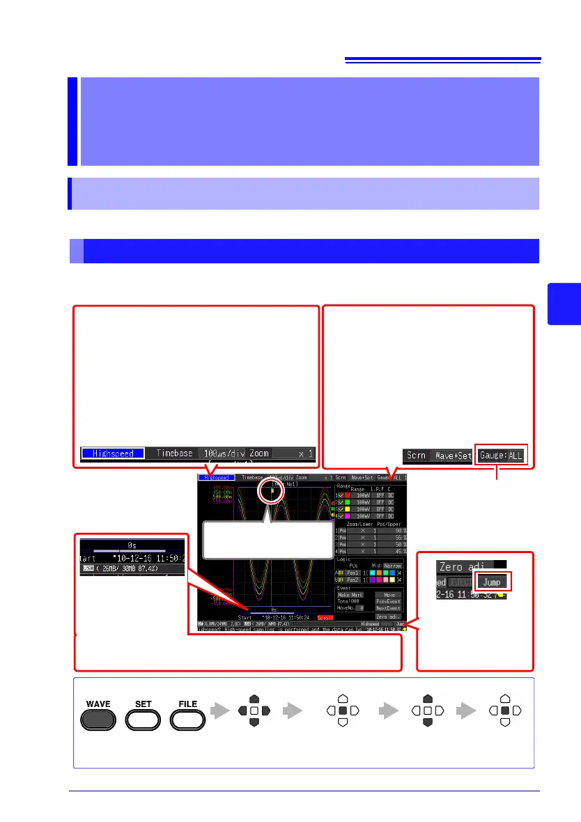
the screen through seven types.
Analog and logic
waveforms
Displays acquired data
as waveforms.
Trigger Mark
Indicates a trigger event
Jump Function
(p. 137)
You can specify the
position you want to
display.
The settings can be changed. (The setting op-
tions are the same as on the Setting screen.)
• Function [Highspeed]/[Realtime]
• When [Highspeed]:
Setting time base range (p. 71) and magnifica-
tion in the horizontal axis direction (p. 89)
• When [Realtime]:
Recording interval (data acquisition interval)(p.
79) and Display time base (time per horizontal
division) (p. 90)
Waveform display type
(default setting: [Wave+Set])
You can switch between five types of
waveform display (p. 25).
• Viewing values of cursors on waveform
(p. 138)
• Viewing numerical calculation result
(p. 177)
In addition, you can switch the display, and
confirm channel and trigger settings on the
Waveform screen.
Move to a
setting item.
Apply
Open the setting
options for the item
to be set
Select from the
listed options.
Setting Procedure
Changing the Gauge
You can display all of the
gauges, and the gauge of
the specified channel (p.
134).
Scroll Bar (p. 133)
Shows the range and
position of the dis-
played waveform.
Information such as measurement start time and trigger times is
displayed below the scroll bar.
 Loading...