1 Connect each of the START terminal or
STOP terminal and GND terminal to the
external signal input destination with electri
-
cal wires.
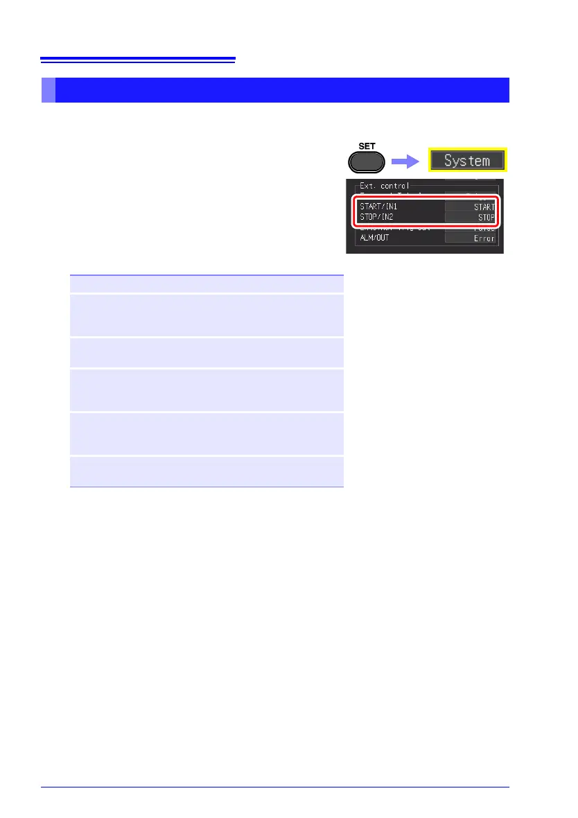
2 Press the SET key to open the [System]
screen.
3 Select the function for each of [START/IN1]
and [STOP/IN2] of external control.
4 Short circuit the terminal and GND, or input a
HIGH level (2.5 to 5.0 V) or LOW level (0 to
0.8 V) pulse wave or rectangular wave to the
EXT.TRIG terminal.
The START/IN1 terminal and STOP/IN2 terminal are
active LOW.
Furthermore, control can be performed by creating
an open or short state between the START/IN1 termi-
nal or STOP/IN2 terminal and the GND terminal.
An open state is equivalent to the HIGH level and the
short state is equivalent to the LOW level.
START Start measurement.
STOP Stop measurement. (Perform post-measure-
ment processing such as numerical calcula-
tion, automatic saving, etc.)
START/
STOP
Start measurement on LOW level, and stop
measurement on HIGH level.
ABORT Force end of measurement. (Do not perform
post-measurement processing such as nu
-
merical calculation, automatic saving, etc.)
SAVE Save to the media specified for the SAVE key,
according to the specified conditions.
(Selection is invalid during execution (p. 202).)
PRINT Perform the same action as the PRINT key.
(Selection is invalid during execution (p. 165).)
See p. 217 for the connection
method.
The initial settings (factory
defaults) are shown below.
• START/IN1: START
• STOP/IN2: STOP
 Loading...