3.2 Setting Measurement Conditions on the Wiring Diagram Screen
45
3
Chapter 3 Connecting to Lines to be Measured
3
3
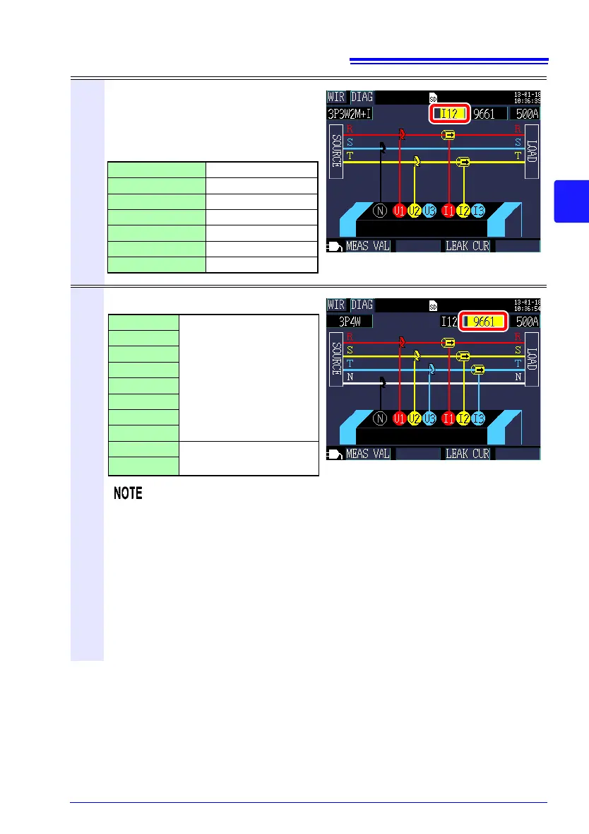
Select the current channel.
To measure multiple circuits with the
wiring, select the corresponding chan-
nel and then set the clamp sensor and
curr
ent r
ange.
4
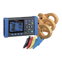
Select the clamp sensor.
• When measuring power lines using multiple channels, combine multiple
clamp sensor types.
For example, when measuring 3-phase/4-wire
lines, use the same clamp
sensor for channels 1 to 3.
• When using the CT9667 Flexible Clamp on Sen
sor, use the same value for
the sensor range setting and the instrument’s clamp sensor range setting.
• When using the 9667 Flexible Clamp on Sensor, select the CT9667.
• The 9657-10 and 9675 leakage current measurement sensors can only be
sele
cte
d when the wiring is set to [I only].
1P2Wx2 I1, I2
1P2Wx3 I1, I2, I3
1P3W+I I12, I3
1P3W1U+I I12, I3
3P3W2M+I I12, I3
I only x 2 (Ix2) I1, I2
I only x 3 (Ix3) I1, I2, I3
9660
Load current (power)
measurement sensors
9661
CT9667-500A
CT9667-5kA
9669
9694
9695-02
9695-03
9657-10
Leakage current mea-
surement sensors
9675