3.10 Setting the Current Sensors
39
3
Chapter 3 Measurement Preparations
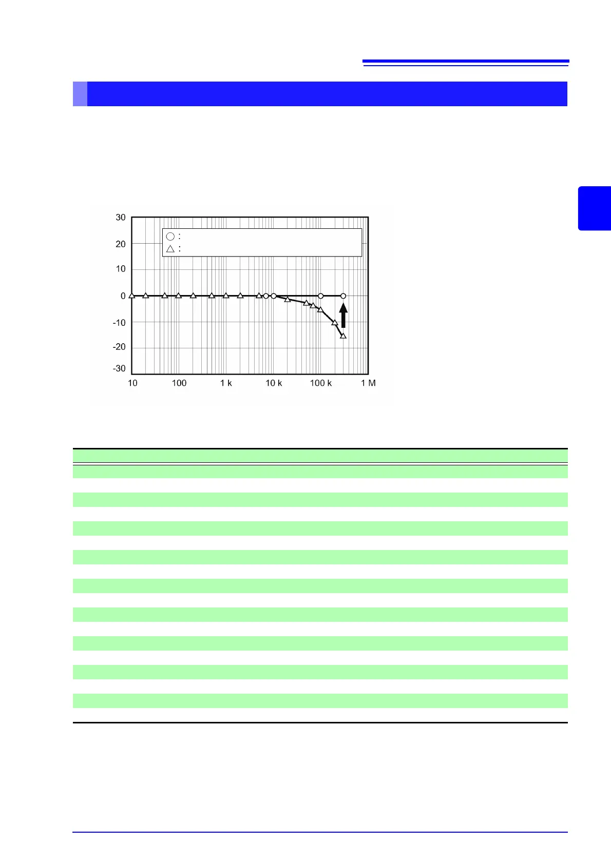
Generally speaking, phase error tends to increase gradually for current sensors in the high-frequency
domain of the frequency band (see illustrative figure below).
Power measurement error in the high-frequency domain can be reduced by using information about the
sensor’s unique phase characteristics to correct phase error.
Representative values for all sensors reflect the following conditions:
• Standard cable length (not using an extended cable)
• Conductor under measurement positioned in the center of the sensor
Configuring current sensor phase correction
Illustrative figure
Phase characteristics after correction
Phase characteristics before correction
Frequency [Hz]
Phase [°]
Current sensor phase characteristics representative values
Model Frequency [kHz] Input/output phase difference representative values [°]
CT6841 100.000 -1.82
CT6843 100.000 -1.68
CT6844 50.000 -1.29
CT6845 20.000 -0.62
CT6846 20.000 -1.89
CT6862 300.000 -10.96
CT6863 100.000 -4.60
CT6865 1.000 -1.21
CT6904 300.000 -9.82
9709 20.000 -1.11
PW9100 300.000 -2.80
9272-05 (20 A) 50.000 -3.34
9272-05 (200 A) 50.000 -4.18
CT7044 5.000 -11.18
CT7045 5.000 -11.90
CT7046 5.000 -13.02
CT7642 1.000 -8.17
CT7742 1.000 -18.62