3.10 Setting the Current Sensors
40
Determine the frequency and phase difference for the sensor to which correction is being applied based on the table of
current sensor phase characteristics (Reference: "Configuring current sensor phase correction" (p. 39)).
(Refer to the “Frequency” column for the frequency and the “Input/output phase difference representative values” column
for the phase difference.)
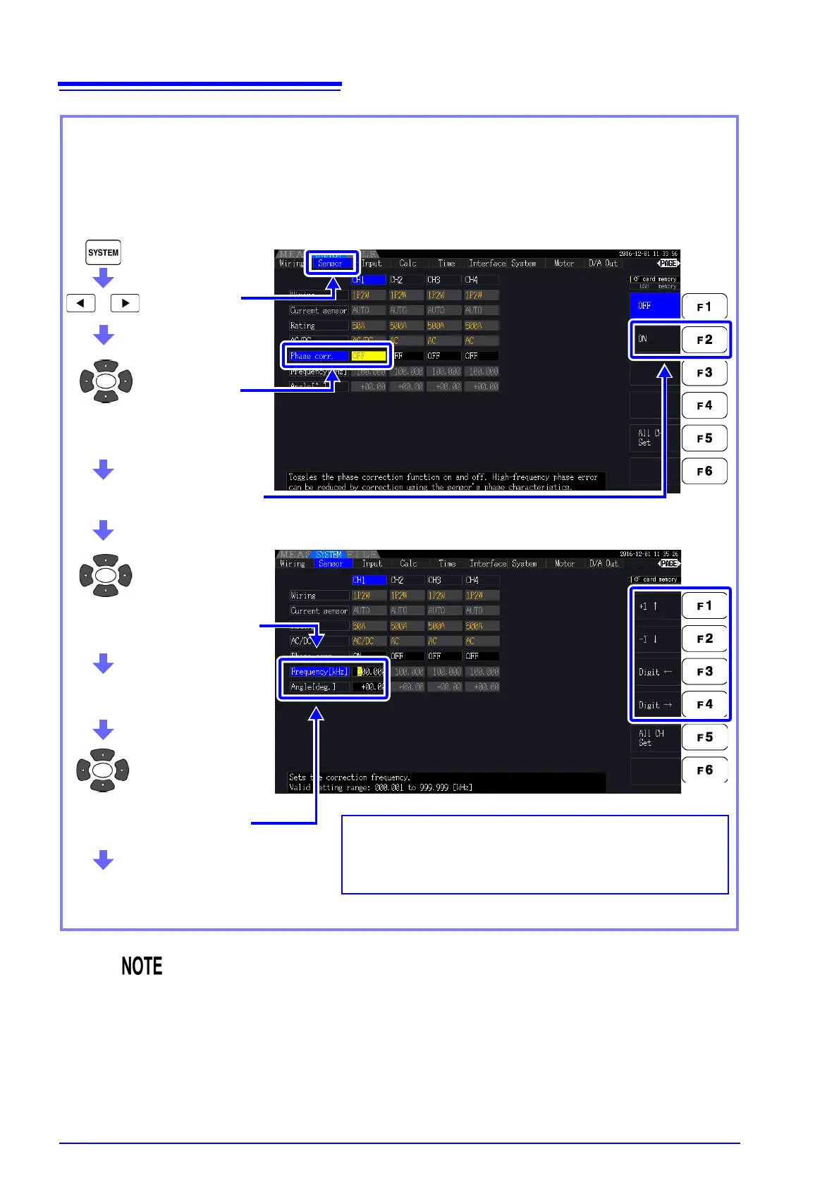
Example for CT6862:
To set a frequency of 300.000 kHz and a phase difference of -10.96°
Display the
[Sensor] page
Select
[ON] with the F2 keys
Select the item
to display
Select a
[Phase corr.]
for the channel being set.
Select [300.000] with the F keys
Select the item
to display
Select a
[Frequency[kHz]]
for the channel being set.
Select a [Angle[°]] for the
channel being set.
Select [-10.96] with the F keys
Method for inputting values using F keys
Select which digit to input with the F3 and F4 keys.
Then increment or decrement the value as desired with the
F1 (+1) and F2 (-1) keys (to select a value from 0 to 9).
• The valid setting range for the angle [°] setting is -90° to +90 ° However, the time dif-
ference calculated from the frequency and phase difference is limited to the range of
-200 s to 200 s, and phase correction calculations are performed at a resolution of
5 ns.
• Set the frequency and phase difference as appropriate for the current sensor in use.
• Use of an improper setting may result in erroneous correction, which may in turn
cause the measurement error to increase. Be sure to enter the settings accurately.