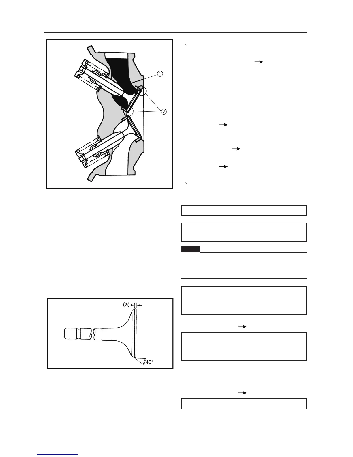
1、CHECK
• valve sealing
Leakage at the valve seat
Check the valve
face, valve seat and valve seat width.
a. Pour a clean solvent into the intake and ①
exhaust ports.
b. Check that the valve seals properly. There
should be no leakage at the valve seat ②.
• valve face
Pitting/wear Grind the face.
• valve stem end
Mushroom shape or diameter larger than the
body of the stem
Replace.
• valve seats
Pitting/wear
Reface the valve seat.
2、MEASURE:
1).Measure:
• The valves surface width
Repairing limit value 2.0mm
• stem-to-guide clearance
Stem-to-guide clearance = valve guide
inside diameter – valve stem diameter
NOTE:
If the mating surface is coarse, corrode or
cannot contact with valve seat normally,
replace it.
Stem-to-guide clearance repairing limit
value
Intake:0.08mm Exhaust:0.10mm
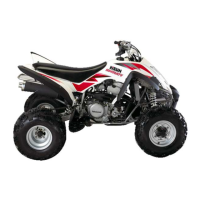
• margin thickness (a)
Out of specification
Replace.
Margin thickness
Intake:2 mm
Exhaust:2.2 mm
• valve stem runout
Out of specification
Replace.
Runout limit 0.01 mm
ENGINE
- 135 -
NOTE:
• When installing a new valve always replace
the guide.
• If the valve is removed or replaced always
replace the oil seal.
• The valve seat surface width
Out of specification Reface the valve seat.
Repairing limit value
2.0mm
a. Install the valve into the cylinder head.
b. Press the valve through the valve guide and
onto the valve seat to make a clear pattern.
c. Measure the valve seat width. Where the
valve seat and valve face made contact, blueing
will have been removed.
• Valve spring free length
• Valve spring squareness
Out of specification
Replace.
Valve spring free length
Intake:44.9mm Exhaust44.9mm
Valve spring squareness
Intake:1.60mm Exhaust 1.60mm
• compressed spring force(a)
Out of specification Replace.
(b) Installed length
Compressed spring force
Intake: 470 N at 24.5 mm
Exhaust: 270 N at 31.0 mm
2). Remove:
• valve guide
NOTE:
To ease guide removal, installation and to
maintain correct fit, heat the cylinder head to
100 °C (212 °F) in an oven.
a. Install the new valve guide using a valve guide
remover ① and valve guide installer ②.
b. After installing the valve guide, bore the
valve guide using a valve guide reamer ③
to obtain proper stem-to-guide clearance.