TROUBLESHOOTING
IF THE FAN MOTOR DOES NOT MOVE:
Procedure
Check:
1. Battery
2. Main switch
3. Radiator fan motor
1. Battery
• Check the battery condition. Refer to
“CHECKING AND CHARGING THE
BATTERY” in chapter 3
。
Open-circuit voltage:
12.8 V or more at 20 °C (68 °F)
CORRECT
2. Main switch
Refer to “CHECKING THE SWITCH”.
CORRECT
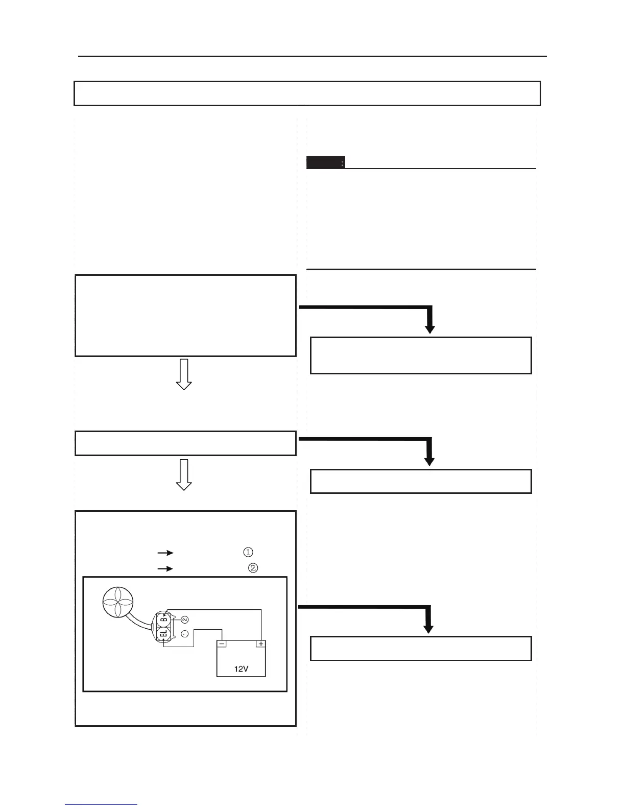
3.Radiator fan motor
• Disconnect the radiator fan motor coupler.
• Connect the battery (12 V) as shown.
Battery (+) lead
Blue terminal ①
Battery (–) lead
Black terminal ②
• Check the operation of the radiator fan
motor.
4. Thermo switch 3
5. Wiring connection(the entire cooling system)
NOTE:
• Remove the following part(s) before
troubleshooting.
1. Console
2. Front frame
3. Front pedal
• Use special tool(s) for troubleshooting.
INCORRECT
• Clean the battery terminals.
• Recharge or replace the battery
INCORRECT
Replace the main switch.
DOES NOT TURN
Replace the radiator fan motor.
ELECTRICAL COMPONENTS
- 261 -
4.Thermo switch 3
• Remove the thermo switch 3 from the
radiator.
• Connect the pocket tester (Ω × 1) to the
thermo switch 3 ①.
• Immerse the thermo switch 3 in coolant ②.
• Check the thermo switch 3 for continuity.
While heating the coolant use a thermometer
③ to record the temperatures.
□
A
The thermo switch 3 circuit is closed.
□
B
The thermo switch 3 circuit is open.
Test
step
Coolant
temperature
Continuity
1
Less than 75±3 °C
(167 ± 5.4 °F)
No
2
More than 75 ± 3 °C
(167 ± 5.4 °F)
Yes
3
More than 68 °C
(154.4 °F)
Yes
4
Less than 68 °C
(154.4 °F)
No
GOOD CONDITION
5. Wiring connection
• Check the connections of the entire starting
system. Refer to “CIRCUIT DIAGRAM”
CORRECT
This circuit is not faulty.
Test steps 1 & 2: Heating phase
Test steps 3 & 4: Cooling phase
WARNING:
Handle the thermo switch 3 with special
care.
Never subject it to a strong shock or allow
it to be dropped. Should it be dropped, it
must be replaced.
Thermo switch 3
28 Nm (2.8 m · kg, 20 ft · lb)
BAD CONDITION
Replace the thermo switch 3
POOR CONNECTION
Properly connect the cooling system.