-242-
ELECTRICAL COMPONENTS
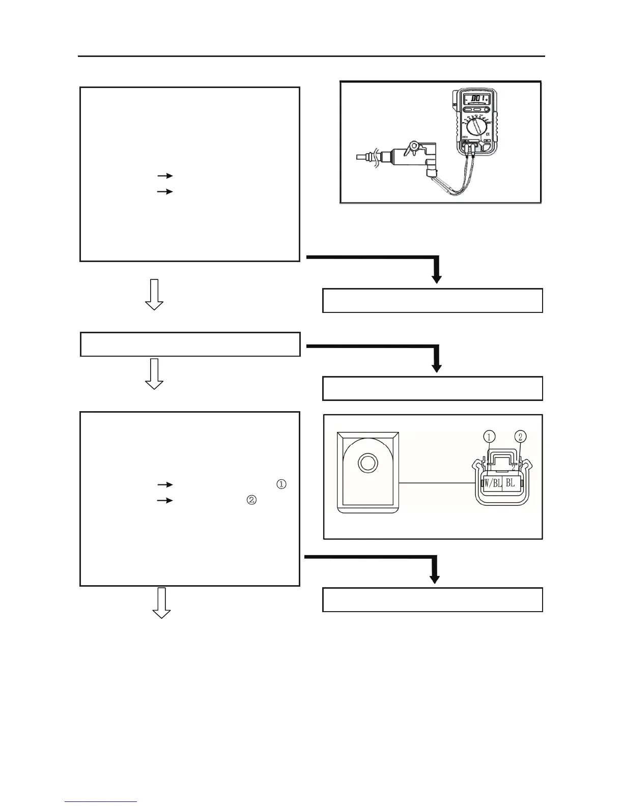
. resistance
Primary coil resistance
0.18 ~ 0.28 Ω at 20 °C (68 °F)
• Connect the pocket tester (Ω × 1k) to the
ignition coil.
Tester (+) lead
Orange lead terminal
Tester (–) lead
Spark plug lead
• Check that the secondary coil has the
specified resistance.
Secondary coil resistance
6.32 ~ 9.48 kΩ at 20 °C (68 °F)
BOTH MEET SPECIFICATION
6. Main switch
Refer to “CHECKING THE SWITCH”
CORRECT
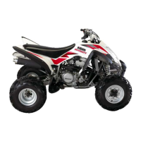
7. Pickup coil resistance
• Disconnect the A.C. magneto coupler from
the wire harness.
• Connect the pocket tester (Ω × 100) to the
pickup coil terminal.
Tester (+) lead White/ Blue terminal ①
Tester (–) lead
Green terminal ②
• Check the pickup coil for the specified
resistance.
Pickup coil resistance
459 ~ 561 Ω at 20 °C (68 °F)
(White/Red – White/Green)
MEETS SPECIFICATION
OUT OF SPECIFICATION
Replace the ignition coil.
INCORRECT
Replace the main switch.
OUT OF SPECIFICATION
Replace the pickup coil/stator assembly.
ELECTRICAL COMPONENTS
- 243 -
8.
Rotor rotation direction detection coil resistance
• Disconnect the A.C. magneto coupler from
the wire harness.
• Connect the pocket tester (Ω × 1) to the rotor
rotation direction detection coil terminal.
Tester (+) lead
Blue/White terminal ①
Tester (–) lead Blue terminal ②
• Check the rotor rotation direction detection
coil for the specified resistance.
Rotor rotation direction detection coil
resistance
0.063 ~ 0.077 Ω at 20 °C (68 °F)
(Red – White/Blue)
MEETS SPECIFICATION
9.Wiring connection
• Check the connections of the entire ignition
system. Refer to “CIRCUIT DIAGRAM”.
CORRECT
Replace the ECU unit
ELECTRIC STARTING SYSTEM
CIRCUIT DIAGRA(
See 292 page)
OUT OF SPECIFICATION
Replace the pickup coil/stator assembly.
POOR CONNECTION
Properly connect the ignition system.