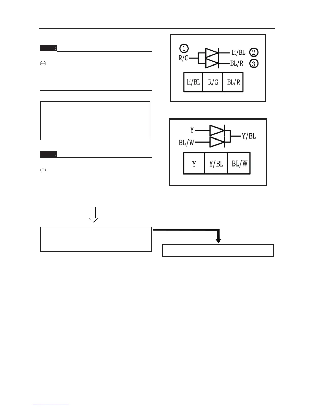
NOTE:
㈠When you switch the tester’s positive
and negative probes, the readings in
the left chart will be reversed.
㈡Connect multimeter positive to Red/Bule
white terminal (1)
Connect multimeter negative to Yellow/Bule
terminal (2)
NOTE:
㈡When you switch the tester’s positive
and negative probes, the readings in
the left chart will be reversed.
CORRECT
8. Wiring connection
• Check the connections of the entire starting
system. Refer to “CIRCUIT DIAGRAM”.
POOR CONNECTION
Properly connect the starting system.
ELECTRICAL COMPONENTS
- 247 -
STARTER MOTOR
No. Part Name Qty Remarks
1
2
Removing the starter motor
Flange bolt
Starter motor assy.
1
1 / 1
Remove the parts in the order listed
CHARGING SYSTEM
CIRCUIT DIAGRAM(
See 293 page)



 To Next Page