5-14
5.8 Head base Replacement Procedure
When damaging the head base, the head base must be replaced. Perform it by the
following procedure.
(1) Remove all of the covers described in the item 5.1.
(2) Remove the nozzle described in the item 5.2.
(3) Remove the deflecting base described in the item 5.3.
(4) Remove the sealing valve described in the item 5.5.
(5) Remove the heating unit described in the item 5.6.
(6) Remove the gutter base described in the item 5.7.
(7) Remove the FG and NH sponges.
(8) Remove the soldering of the APH sensor board and the signal wire.
(9) Unscrew the APH sensor board setscrew.
(10) Unscrew the fastening screw between the head base and the head cable, and remove
the head base.
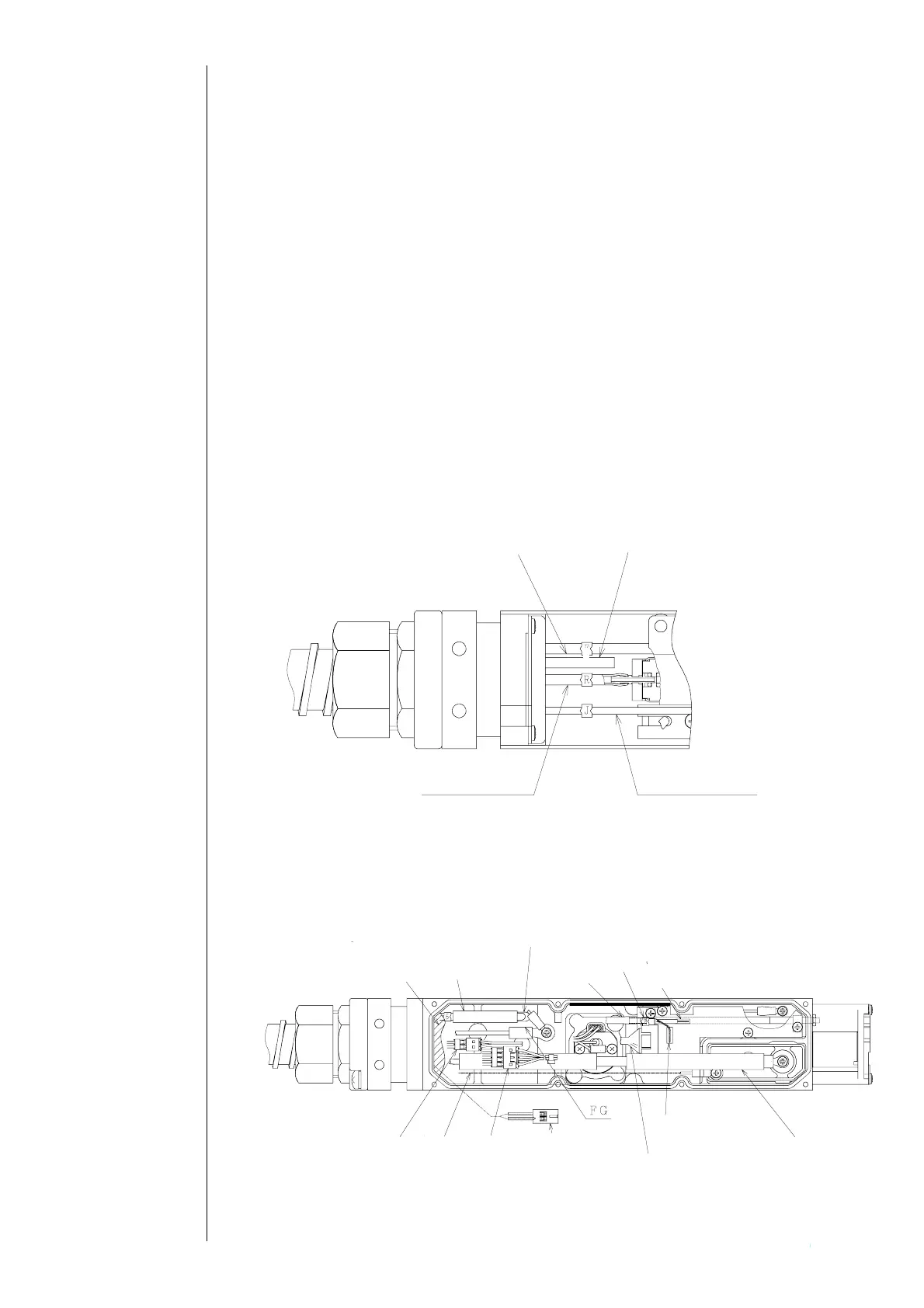
(11)Attach a new head base.
“Caution”
①Do not mix up lead wires and tubes which each is disposed on the front face
(nozzle side) and the back face (high voltage cable side).
Front face: ink-furnishing tube (E), washing tube (R), circulating tube (J), air
purge.
Back face: excitation signal wire (pull it out from the head base opening to the front
face),
G, sealing valve feeder wire, recovery tube, APH signal wire, video
signal wire, heater feeder wire, cover SW signal wire, EZJ98 board
signal wire, high voltage feeder wire
Pull the excitation signal wire out from the opening to the front face
Sponge
Excitation
APH
Signal side
soldering
Sealing valve
Video
Heater
Cover SW
GND side
soldering
High voltage
EZJ98 CN1 signal wire
Recovery
Ink-furnishing tube (E)
ir purge
E
Washing tube
Circulating tube