4-19
4.10 Print Head Replacement Procedure
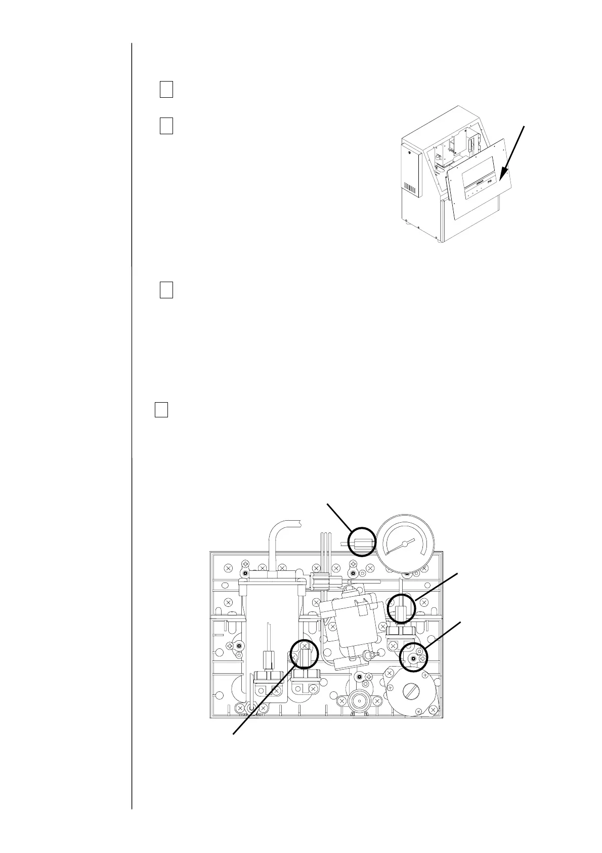
1 Turn off the power supply.
2Remove the operation panel,
and then hang it on the unit.
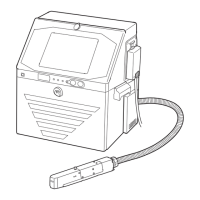
3
Remove the print head and the connectors (6 positions).
(a) High-voltage wire (high-voltage power supply part)
(b) APH signal wire (EZJ94 board: CN2)
(c) Charged signal wire (EZJ94 board: CN3)
(d) Excitation signal wire (EZJ94 board: CN5)
(e) Cover switch, etc. (EZJ94 board: CN7)
(f) FG (grounding) wire
4 Remove the piping connections (4 positions) with the print head.
(Loosen the tube lock and pull out the tube.)
"Caution" Put wiping paper at the end of the tube to provide for an ink drip.
Circulation line
(Pipe signal: J)
Collection line
(Pipe signal: A)
Supply line
(Pipe signal: E)
Makeup ink line
(Pipe signal: R)
Operation panel
Caution:
Be careful that the wire harness does
not get caught on anything.
Do not hang the panel with the
maintenance cover open for a long time
(less than 10 minutes allowed): Leaving
it hanging more than 10 minutes could
deform the packing.