3-3
3.2 Controller part
●This section shows the functional overview of electric parts/control board in the
controller block, switch settings, a list of check points/LEDs, and cautions on
replacement.
3.2.1 EZJ102 board (controller board)
【Function】
●Creates print data and manages it.
●Manages calendar.
●Controls the display block.
●Controls Memory card (CF card).
●Controls the touch panel.
●Internalcommunication I/F with engine block.
●The I/F signal with conveyer are connected.
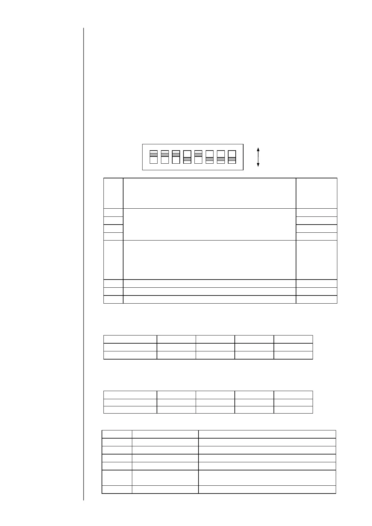
[SW1]
SW1
Setting
Default
(when
shipped from
the factory)
Bit1
Set according to the encoder specifications.
ON
Bit2
(See the settings for different specifications shown below.)
ON
Bit3 ON
Bit4 OFF
Bit5
Set the power supply from IJ printer to print target
sensor.
・When supplying power from IJ printer: Set to ON
・When supplying power from external exclusive power:
Set to OFF
ON
Bit6
Spare (Set to OFF)
OFF
Bit7
Spare (Set to OFF)
OFF
Bit8
Spare (Set to OFF)
OFF
・When supplying power from IJ printer:
Set SW1 as shown in the table below according to the output type of
rotary encoder:
Output type
SW1-1 SW1-2 SW1-3 SW1-4
Totem-pole
OFF ON ON ON
Open collector
ON ON ON OFF
・When using external exclusive power supply:
Set SW1 as shown in the table below depending on the power voltage,
regardless of the output type of rotary encoder:
Power voltage
SW1-1 SW1-2 SW1-3 SW1-4
DC12V OFF ON ON OFF
DC24V OFF OFF ON OFF
●Check points/LED
Symbol
Name Content
TP4 MTXD
Engine communications (send data)
TP5 MRXD
Engine communications (receive data)
TP7
Encoder-N Encoder input (“L” when signal is input)
TP8
Print target sensor-N Print sensor input (“L” when signal is input)
TP9
Floating
GND
Reference ground of external photocoupler
insulating circuit (on conveyer side)
TP60
GND Reference ground of IJ printer-side circuit
ON
OFF
ON
4321 8765