5-2
5.2 Nozzles Replacement Procedure
(appendix: nozzle drive conditions)
(1) Depressurize the printer.
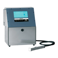
(2) Unscrew the video signal wire setscrews and the charged electrode setscrews, and
remove the charged electrode.
(3) Remove the nozzle setscrew (2 locations), the nozzle IN joint presser foot
(sealing valve side) and the excitation connector.
“Caution” A filter is put in the terminal area (inside the sealing valve) of the nozzle IN
joint and therefore, be careful about dropout.
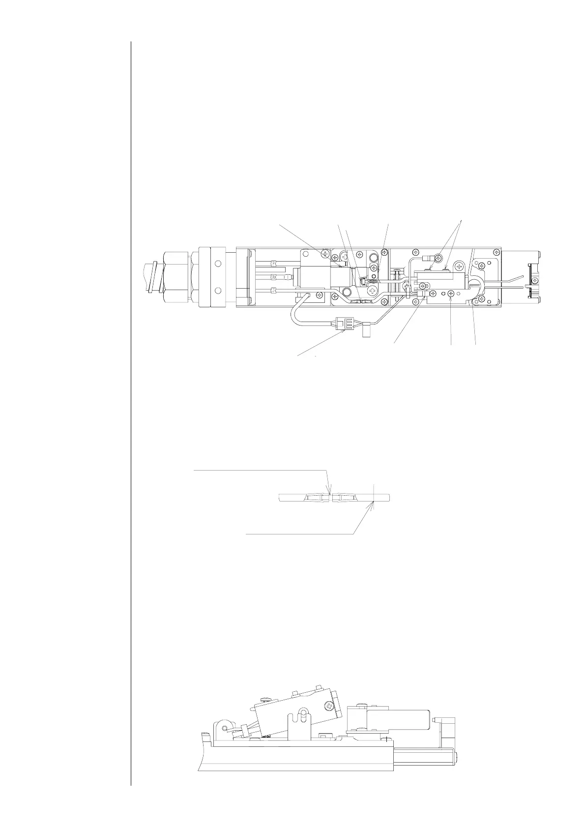
(4) Cut off the nozzle side of the nozzle OUT joint by a cutter or the like.
“Caution” When removing the nozzle OUT joint, remove it so as not to pull the
main body side tube.
"Caution"
①If you scratch the coupling with a cutter or the like, it may cause an ink leakage
and so on.
②When removing a cut piece of the tube, cut the tube piece and pull it off the
coupling.
(5) Pull out the nozzle upward with a slope while taking up the front edge of the nozzle.
Sealing valve
Nozzle OUT
oint
Filter
Nozzle IN joint
presser foot
Nozzle setscrew
Excitation
connector
Video signal
wire setscrew
Charged
electrode
setscrew
Char
ed electrode
Nozzle OUT joint presser foot
←Main body side
Nozzle side→
Cut off this part
Pull out the nozzle upward with a slope→