5-3
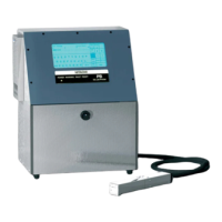
(6) Attach a new nozzle and fix the nozzle setscrew, (2 locations), the nozzle IN
joint presser foot (sealing valve side), the nozzle OUT joint and the excitation
connector.
“Caution”
①Confirm that a filter is present in the terminal area (inside the sealing valve) of
the nozzle IN joint.
②Wet the insert portion inside the sealing valve with the intensifier to make it
slippery and then, connect the nozzle IN joint.
“Caution”
If connection is imperfect, ink will below off.
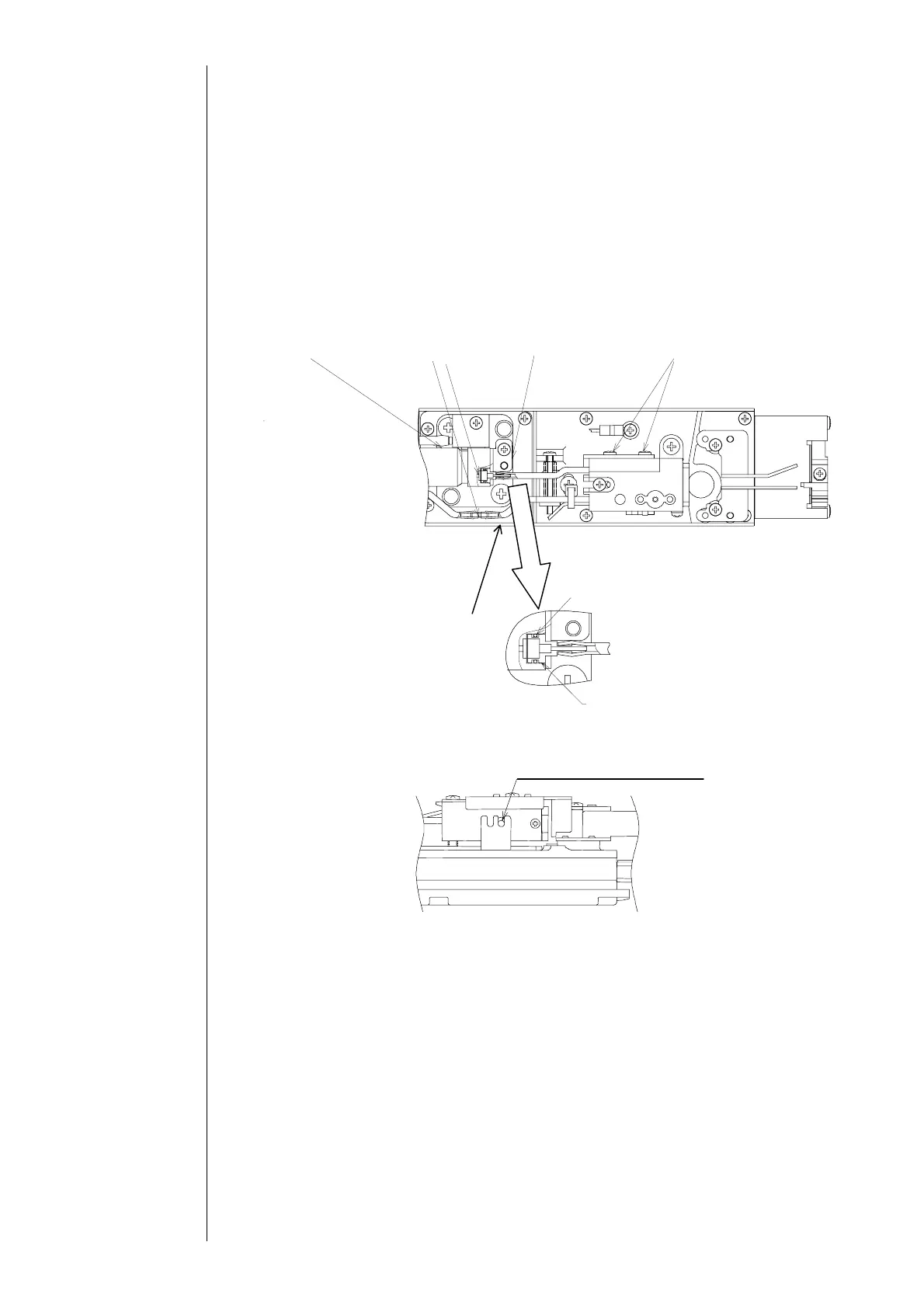
The nozzle attach the position as shown below:
(7)
Cut the recovery side tube of the new nozzle into a suitable length and connect the
nozzle OUT joint.
“Caution”
①Get rid of the tube remaining on the joint in the (4).
②When the tube is hardly put in the joint because it slips, grasp the front edge of
the tube by a JK wiper or the like and put it in the joint.
(8) Put the charged electrode in the new nozzle and fix the video signal wire on the
charged electrode.
(9) Put the charged electrode in the new nozzle and fix the video signal wire on the
charged electrode.
“Caution”
①If you repeat beam adjustment, it will be diluted. Complete it by the third time.
(10) Perform “excitation voltage” and “auto phase gain adjustment” on the picture of
“adjustment/operation confirmation”.
(2 locations)
Recover
side tube
Sealing
valve
Nozzle out
oint
Filter
Nozzle IN joint
presser foot
Nozzle setscrew
O-ring P3.9
Take in the stepped part
Nozzle attachment position