5-10
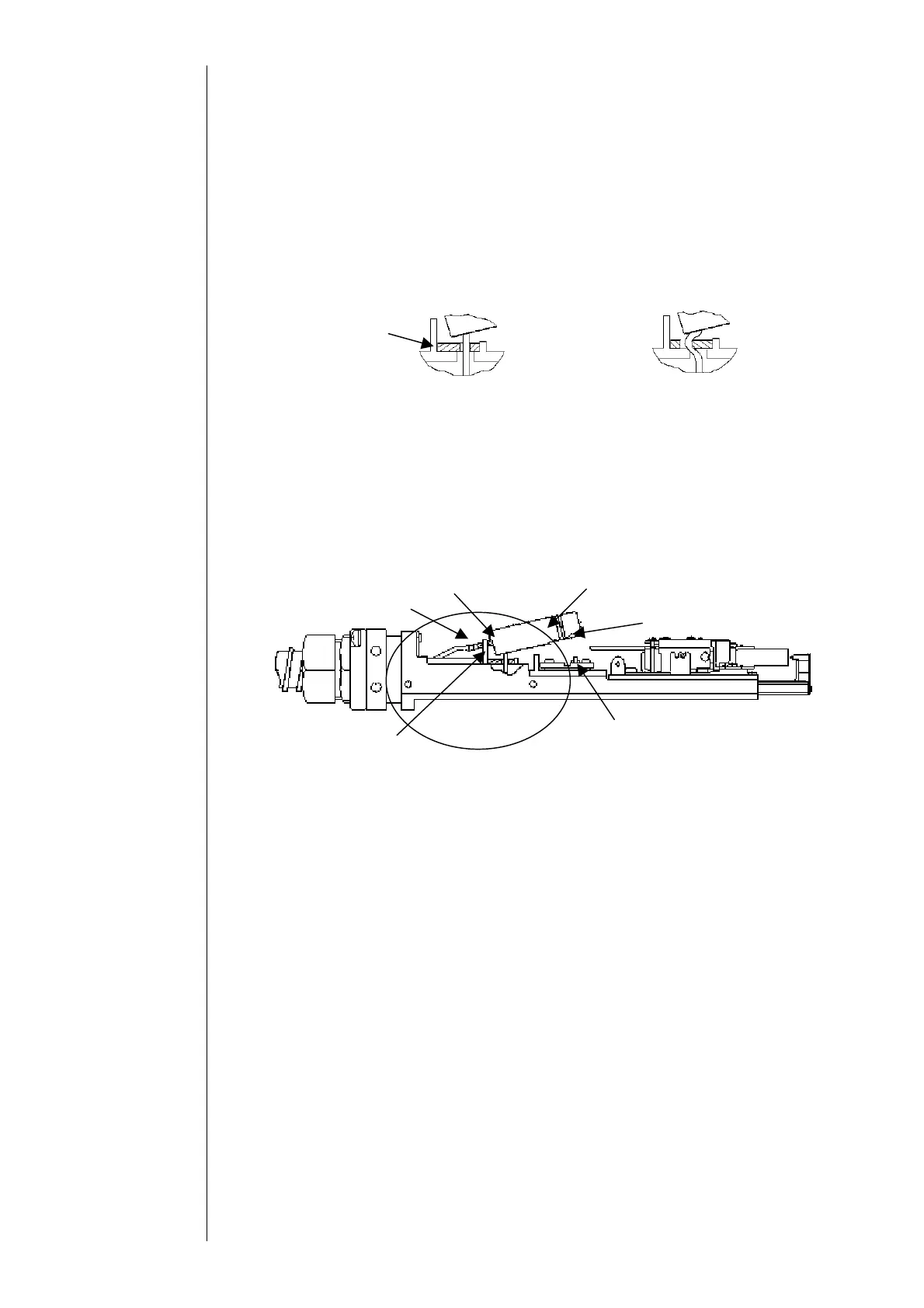
(6) Prepare a new sealing valve and put O-rings into the respective holes of the joint part.
①Put the O-ring P2.2 (hole diameter: about f 2.1) into the hole on the heating unit side
and put the O-ring P1.7 (hole diameter: about
f 1.6) into the hole on the intensifier IN
side.
②Be sure to put the O-rings so as not to jump out of the hole of the joint part.
(7) Put the sealing valve packing into the sealing valve lead wire and set it to a
predetermined position of the head base.
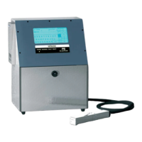
①Be careful to the direction of the sealing valve packing.
(8) Connect the intensifier IN joint to the sealing valve and fix it to the boss on the heating
unit.
①Put the makeup ink IN joint in the groove of the head base rib.
②Perform the assembly after putting the makeup ink on the O-ring, and confirm that
the O-ring does not jump out of the hole.
③Be careful not to apply the makeup ink to the A portion below.
(9) Attach the sealing valve presser foot and fix the sealing valve.
(10) Put the filter and the nozzle IN joint in this order and fix it by the nozzle IN joint
presser foot.
①Refer to the nozzle replacement work sequence.
(11) Assemble the sealing valve connector and attach the head base rear cover.
①Surely put the packing into the groove and attach the cover.
②Be careful so as not to pinch the lead wires.
(12) Spurt ink after the assembly and confirm that there is no leak from each terminal
area.
(13) Attach each cover.
○
×
Sealing valve packing
Makeup ink IN joint
Sealing valve
O-ring P2.2
Heating unit boss
O-ring P1.7
Head base rib
A parts