MX8000 Installation and Operation Guide
1–2
Table 1–1: Optional Accessories for the MX8000 Receiver
Item
ADEMCO Model Number
(if applicable)
Description/Comments
Three Line card MX8000–LC3 The 3 line card monitors the phone lines, detects ring and processes the
message from the communicating panel.
One Line card MX8000–LC1 The 1 line card monitors a phone line, detects ring and processes the
message from the communicating panel.
Radio Line card MX8000–LRR The radio line card interfaces to a transceiver and processes the message
from the communicating panel.
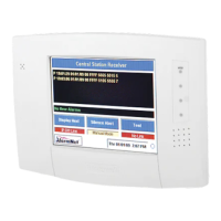
CPU, PS, User
Interface
MX8000–CPU The CPU, Power Supply, User Interface Assembly contains the VFD, main
processing board, and receiver power supply.
Backup battery Acquire from a local retailer
(See Section 3.12 for
installation.)
A UL Fire Protection Services approved 12VDC 7AH battery such as a
Powersonic PS-1270 that will provide a minimum 4 hours of backup power
during an AC power loss. (See Section 2.4.2 for UL backup power
requirements.)
Printer cable Acquire from a local retailer A standard 25-pin cable used to connect the MX8000 receiver to an external
parallel printer.
SBUS cable Acquire from a local retailer A standard 4-wire RJ-11 reverse cable such as a Digi-Key H2642-14-ND that
is used to connect the receivers together for receiver linking.
Rack-mounting
cabinet
Acquire from a local retailer Used to rack mount the MX8000 receiver as required by UL. (See Section
2.4.1 for specifications and vendor information.)
Blank filler panels Acquire from a local retailer Used to fill up any unused cabinet spaces as required by UL.
Parallel printer Acquire from a local retailer The ADEMCO MX8000 receiver requires a UL approved dot matrix parallel
printer such as the Okidata Microline 320 to generate a hardcopy of report
history.
1.3 Formats Compatible with the MX8000
The MX8000 receiver is compatible with all ADEMCO UL Listed communicators.
Table 1–2 shows the formats that the MX8000 receiver can decode and the handshake frequency groups that
accommodate that format (see Section 5.5 for line device programming). Each line device can decode every
format listed below. Setting the handshake order only prioritizes the type of communication done by each
line device. Section 6 of this manual describes the formats in greater detail.
Important Note: When selecting a reporting format and using an automation computer, it is essential that
you check Table 8–2: Reporting Formats and Automation Protocol Support to verify that the reporting format
selected is supported by the automation protocol that will be used.
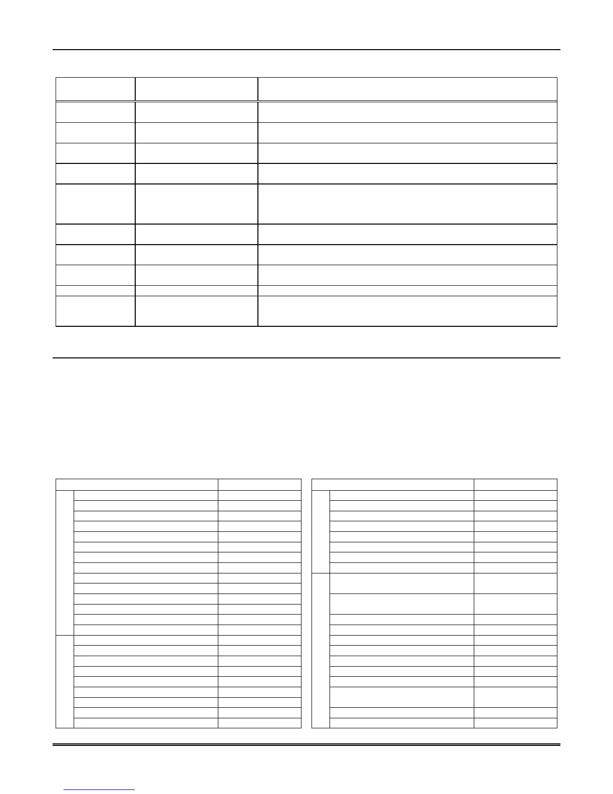
Table 1–2: Formats Compatible with the MX8000
REPORTING FORMAT PPS or CPS
REPORTING FORMAT PPS or CPS
3/1, 3/1 Ext 10, 20, or 40 PPS ITI UltraGard N/A
3/1 Even Round 10, 20, or 40 PPS Radionics Modem II N/A
3/1 w/cksum 10, 20, or 40 PPS Radionics Modem IIE N/A
3/1 Ext w/cksum 10, 20, or 40 PPS SIA DCS N/A
3/2 10, 20, or 40 PPS SX-III, SX-IVA N/A
3/2 Even Round 10, 20, or 40 PPS SX-IVB N/A
3/2 w/cksum 10, 20, or 40 PPS Varitech FSK 4/1 N/A
4/1, 4/1 Ext 10 PPS
FSK (cont’d)
Varitech FSK 4/2 N/A
4/1 Even Round 10 PPS
4/1 w/cksum 10 PPS
Acron Touchtone w/ 3-digit
account
10 CPS
4/1 Ext w/cksum 10 PPS
4/2 10 PPS
Acron Touchtone w/ 4-digit
account
10 CPS
4/2 Even Round 10 PPS ADEMCO 4/1 w/cksum 10 PPS
1400/2300 Hz Pulse
4/2 w/cksum 10 PPS ADEMCO 4/2 w/cksum 10 PPS
BFSK N/A ADEMCO High Speed 10 CPS
FSK0/FSK 80 N/A ADEMCO High Speed w/cksum 10 CPS
FSK1/FSK 81 N/A Contact ID® 10 CPS
FSK2/FSK 86 N/A Contact ID®10 10 CPS
ITI CareTaker+, SecurityPro 4000 N/A FBII 4/3/1 10, 20, or 40 PPS
ITI Commander N/A
ITI Commander 2000, LifeGard N/A
FBII 4/3/1 w/cksum
FBII Superfast
10, 20, or 40 PPS
ITI RF Commander, Harbor Gard N/A Westec 970 10 CPS
FSK
ITI SX-V N/A
DTMF
Westec 1000/2000/3000 10 CPS
 Loading...