Section 1 – System Overview
1–3
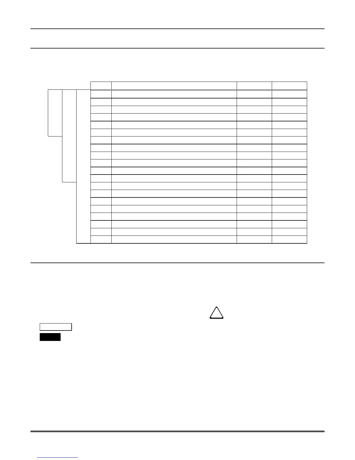
1.4 MX8000 Supported SIA Digital I-III Levels
Table 1–3 compares the MX8000 receiver to SIA Digital Compatibility Levels I, II, and III and indicates
which of them we comply with.
Table 1–3: MX8000 and SIA Levels I-III comparison
8000 Function/Capability Transmitter Receiver
✔
Support Tonal Acknowledgments required required
✔
Support N blocks with Zone Numbers Only required required
✔
Support single Account Block per Call required required
✔
Support O Blocks (optional) required
✔
Support X Blocks (optional) required
Level I
✔
Support 300 Baud (Fast) (optional) required
Support Configuration Block required required
Support Data Acknowledgments required required
✔
Support Modifier codes
id
,
da
and
ti
. (optional) required
✔
Support Multiple Account Blocks per Call (optional) required
✔
Support E Blocks (optional) required
Level II
✔
Support Data Codes with Units Numbers (optional) required
Support RECEIVER call out and Access Passcode required required
Support Reverse Channel C Blocks required required
Support Reverse Channel P Blocks required (optional)
Support Reverse Channel A Blocks (optional) required
Support Dynamic block and Group Sizes (optional) required
✔
Support Listen-in (optional) required
✔
Support A Blocks to RECEIVER (optional) required
Level III
Support V-Channel communication (optional) (optional)
1.5 How to Use this Manual
This manual contains information on how to install, operate and program the MX8000 receiver. We strongly
suggest that the manual be reviewed in its entirety to become familiar with procedures and parameters of
the product. Once you are familiar with the product, the manual can be used as a reference document.
This manual uses the following conventions:
• A small graphic of each touchpad button is used to represent which touchpad key is to be pressed for a
given operation. For example, an up-arrow would be shown as:
• VFD display This represents messages that appear on the VFD (display).
• 2225Hz This typeface represents an editable field that appears on the VFD (display).
• Pages of the manual are numbered by section. For example, a page numbered as “5-1” is Page 1 of Section
5.
• When this manual refers to default settings, it means programmable options set at the factory. Any
programming after the receiver is powered up will change these setting.