MX8000 Installation and Operation Guide
3–8
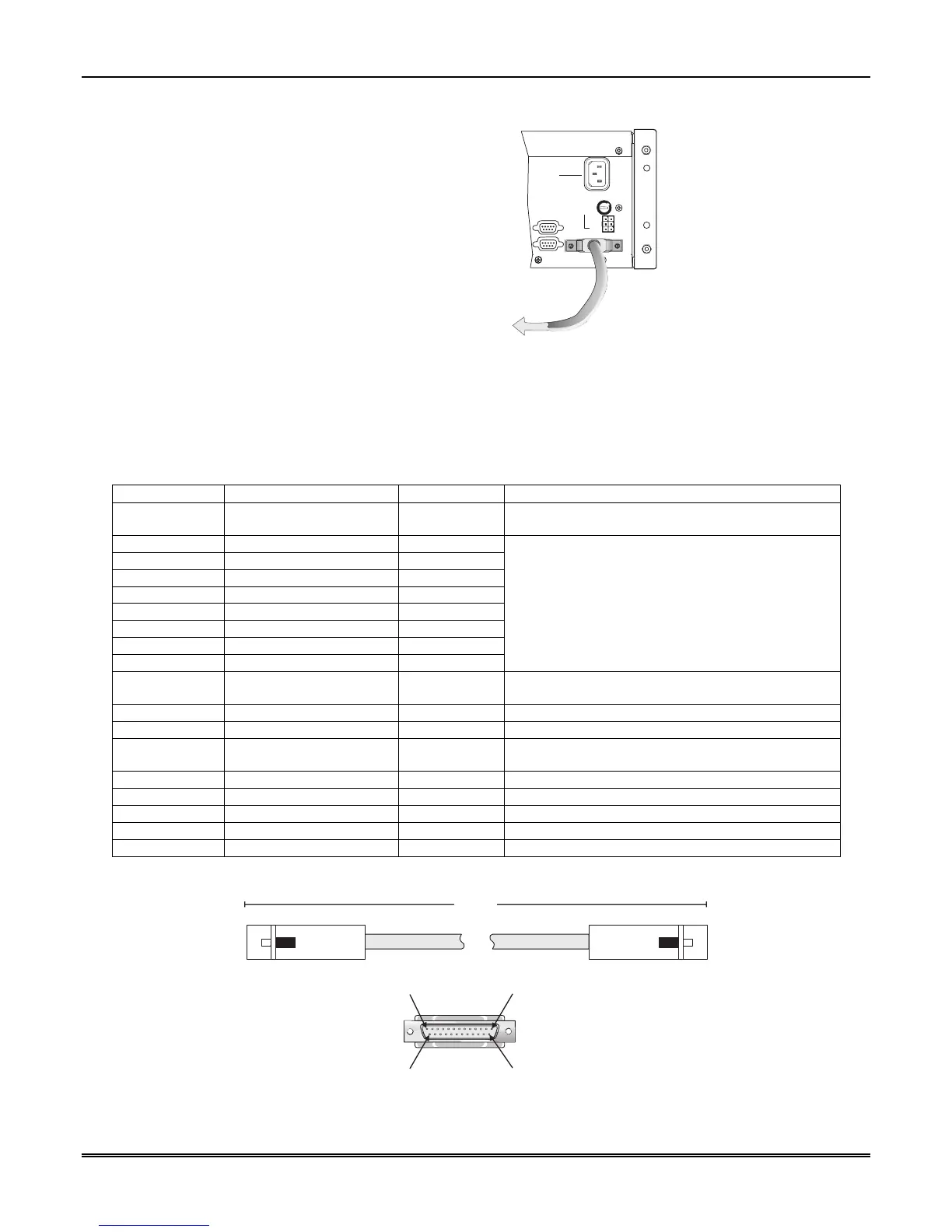
3. Turn the printer power “on”.
TO PRINTER
NOTE:
FOR UL APPLICATIONS, A
STANDBY PRINTER MUST
BE AVAILABLE TO BE PUT
INTO OPERATION WITHIN
30 SECONDS. ONE STANDBY
PRINTER MUST BE AVAILABLE
FOR EVERY 5 PRINTERS.
COM 1
PARALLEL
100 VA
120 VAC ± 10%
240 VAC ± 10%
50-60 Hz
WARNING!
HIGH VOLTAGE PRESENT
DISCONNECT AC LINE AND
ALL OTHER CONNECTORS
PROIR TO SERVICING
FUSE
2.5A
SLOW BLOW
REPLACE ONLY
WITH A FUSE
OF SAME TYPE
UNUSED
RLY NO
RLY COM
BATT-
BATT+
RLY NC
COM 2
RELAY RATING
2.5A 48VAC/VDC
Figure 3–8: Parallel Printer Cable Connection to MX8000
3.10.1 Printer Cable Pin-Outs
25 pin printer cables are standard items at most electronic stores; however, if you create your own cable, use
the pin description in Table 3–1.
Table 3–1: External Printer Cable Pin Description
MX8000 Pin # Signal Direction Description
1 Data Strobe (Low) Out A low strobe pulse to read data into the printer. The
pulse width is greater than 0.5 microseconds.
2 Data Bit 1 Out
3 Data Bit 2 Out
4 Data Bit 3 Out
5 Data Bit 4 Out
6 Data Bit 5 Out
7 Data Bit 6 Out
8 Data Bit 7 Out
9 Data Bit 8 Out
These signals represent information of the first to
eighth bits of parallel data. Each signal is at high
level when the data is logic 1 and low when it is
logic 0.
10 /AckNlg In A low pulse from the printer signals the control that
the printer is ready for additional data.
11 Busy In A high level indicates that the printer is busy.
12 Paper Empty In A high level indicates that the printer is out of paper.
13 Select In A low level indicates the printer is offline or in an
error condition.
14 Not used - -
15 Not used - -
16 Logic ground - Logic ground for printer
17 Not used - -
18 to 25 Logic Ground - Ground return for data lines.
Figure 3–9 shows the wiring sequence of this connector.
Pin 1 Pin 13
Pin 25Pin 14
10.0'
Receiver
Printer
MX8000
NOTE:
10' is the
maximum
recommended
cable length.
Figure 3–9: Wiring Sequence For Parallel Printer Port Interface